
Spectrum +2B with internal IDE Interface
The Spectrum is a great machine but loading games takes upwards of 10 minutes and even on a +3 machine with a disk drive still takes minutes and thats if the disks still work after 30 plus years of use.
I therefore decided to build something to improve the retro experience on this machine.
Enter the universal ide interface
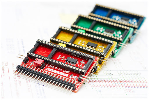
This plugs directly to the Z80 processor socket with the Z80 plugged into it.
With custom +3e Roms installed you can connect IDE hard drives and compact flash cards.
I decided to go down the compact flash card route as it is easier to install internally with limited space.
Plus this can be used in all Spectrum models.
The result is staggering with the interface able to handle compact flash cards upto 2GB which can easily accommodate every bit of software ever written for the Spectrum.
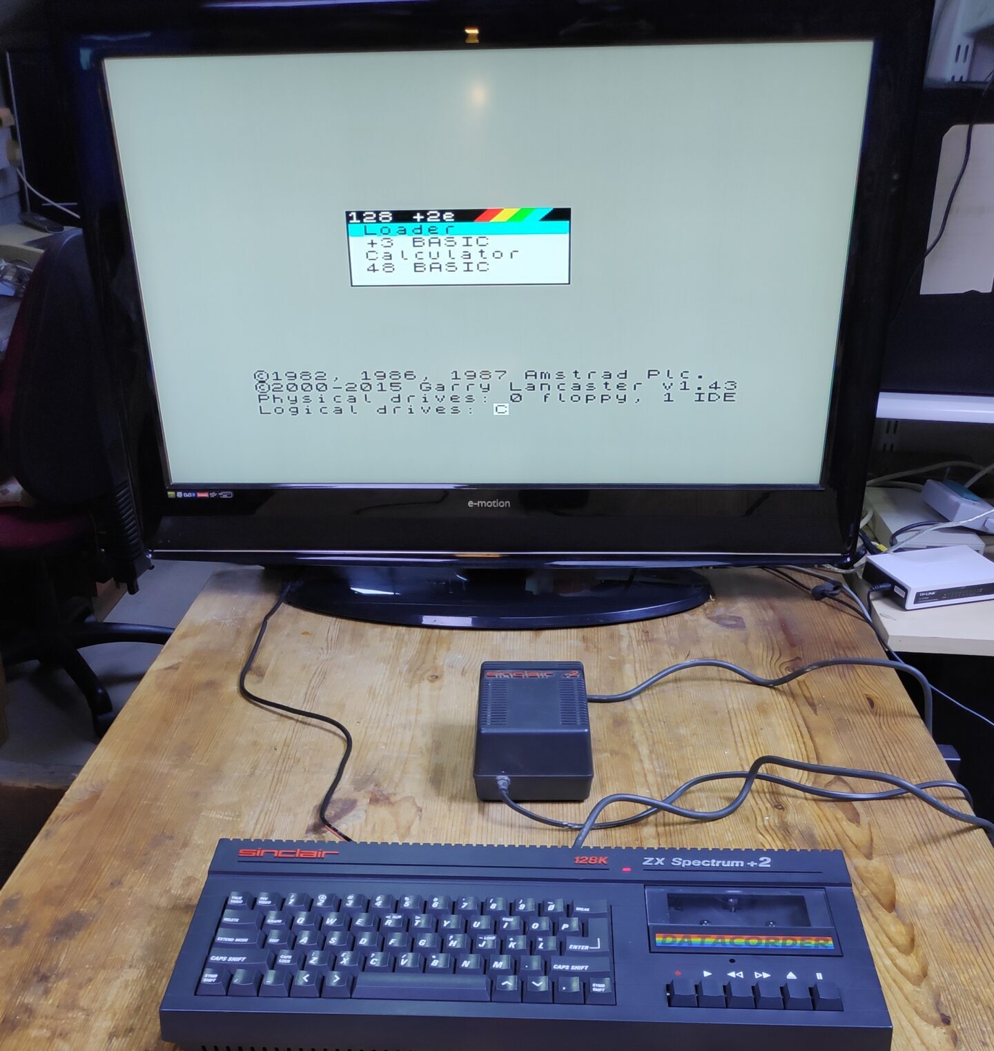
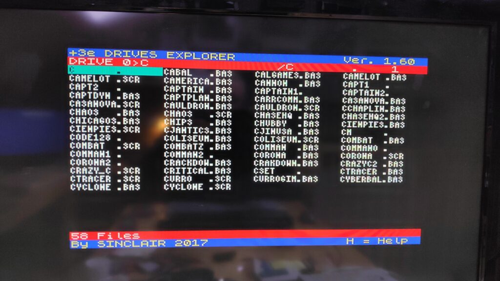
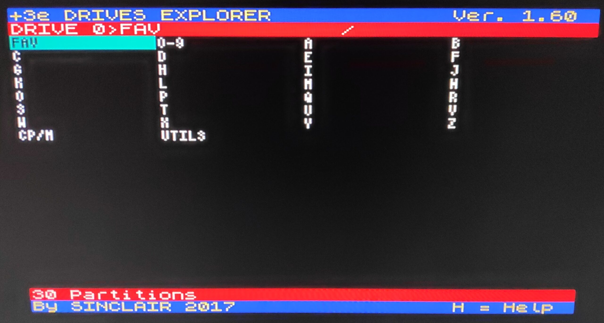
I also installed game launcher software which allows you to easily access and manage all installed software and is immediately available when turning on the Spectrum. Just select “Loader”.
Loader loaded.
Games now load in just a few seconds
Available to buy here https://www.retronerd.co.uk/product-category/sinclair/
Details installation instructions are below.
Installation is done at your own risk and I do not take any responsibility for any damage you may do to your Spectrum, so take your time and be careful!
Installation
Disconnect all cables from your Spectrum
Turn your spectrum upside down and remove the six screws on the underside of the Spectrum
Hold the top and bottom together and Turn the Spectrum right side up
Carefully lift the right (Tape Deck) side top case and be careful not to pull the tape deck cable. You will be able to unplug the the cassette cable while lifting the top case.
Now you can lift the top case fully from the right side but be careful not to stretch the keyboard connectors on the left side. While leaving the left side down carefully open the right side top case fully and lay it beside the bottom case , like opening a book.
You can remove the keyboard connectors by prying them out with finger and thumb gripping each side of the connector and CAREFULLY! lifting out one side then the other bit by bit. It is not essential to remove the keyboard connectors but it ensures they don’t get stretched and pulled while installing the interface.
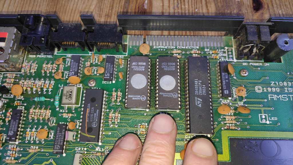
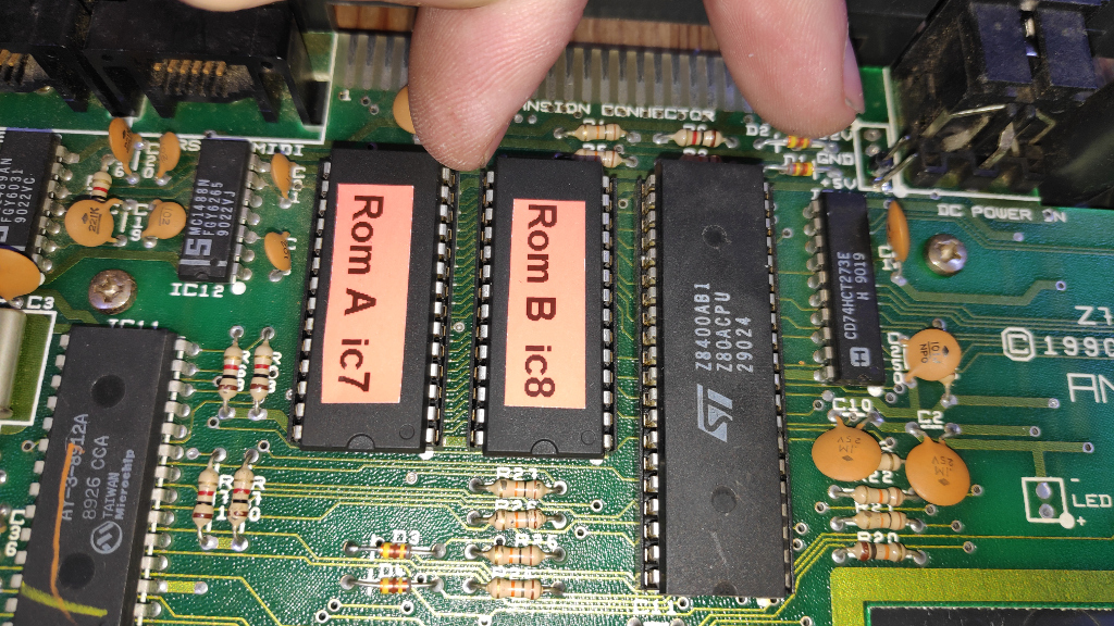
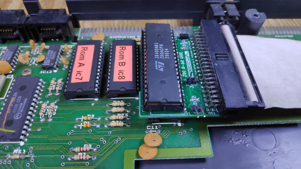
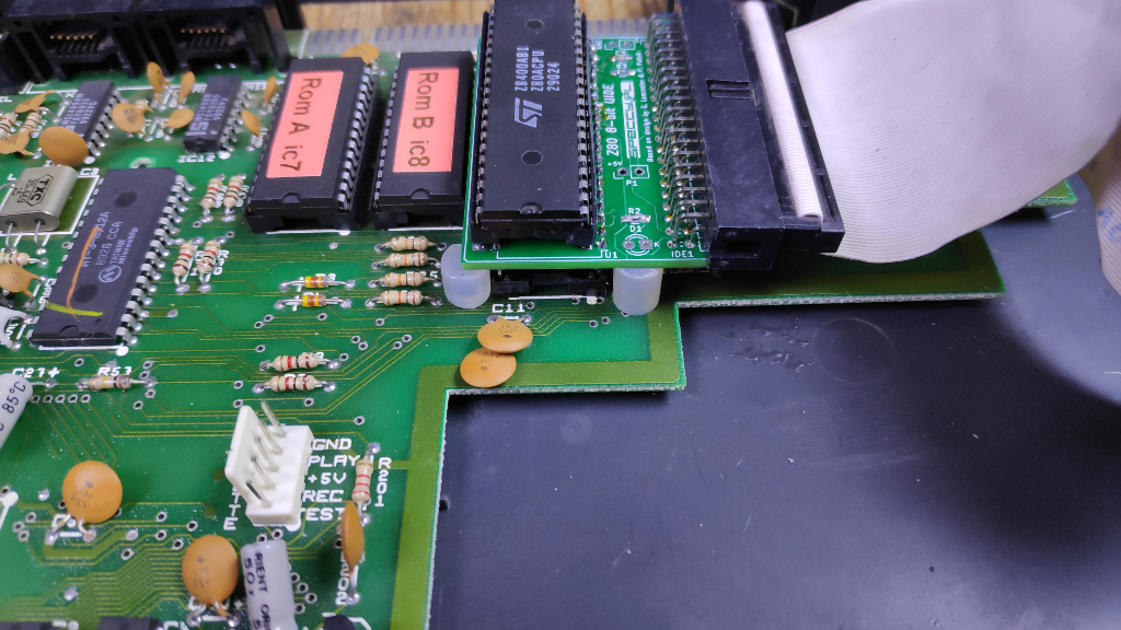
Below is the three chips which need removing. Left to right is Rom A, Rom B and the Z80 CPU on the right. Carefully pry these out using a flat blade screw driver or other flat implement. In small increments slightly lift one end then the other until the chip pops out.
You can install the new Rom chips at this stage. Note the notch on the chip faces the bottom. See below
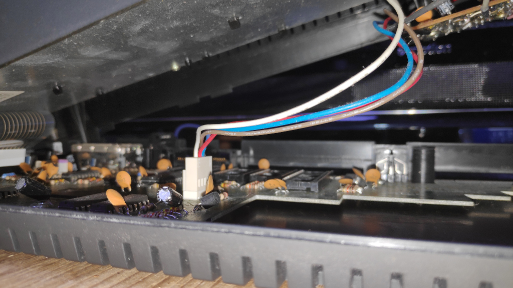
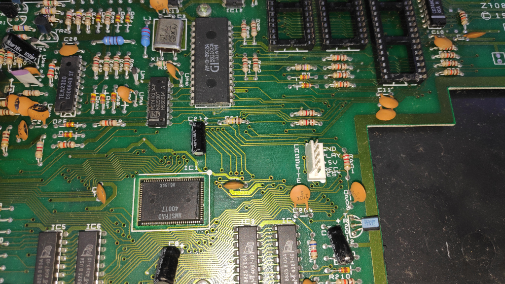
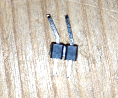
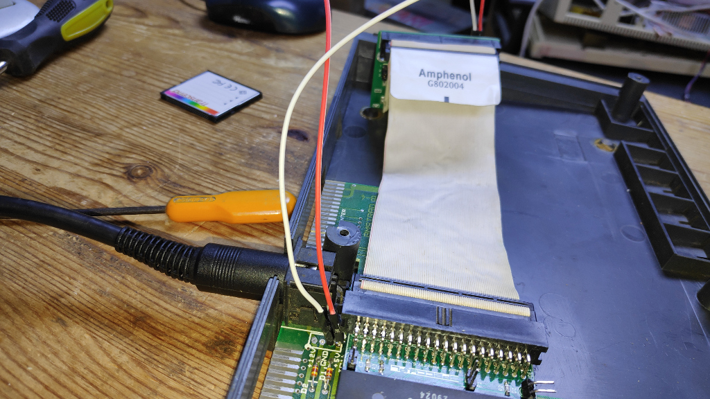
You can choose to solder 2 pins (5v, Ground) on the board or optionally connect to the Cassette Port. The first photo shows where to solder the pins to Ground( marked GND on the board) and 5v. The second photo below shows the Cassette port to connect to Top pin Ground(GND) and middle pin 5V for the non solder method. The Tape Deck will obviously not be available unless the cable is replaced on reassembly.
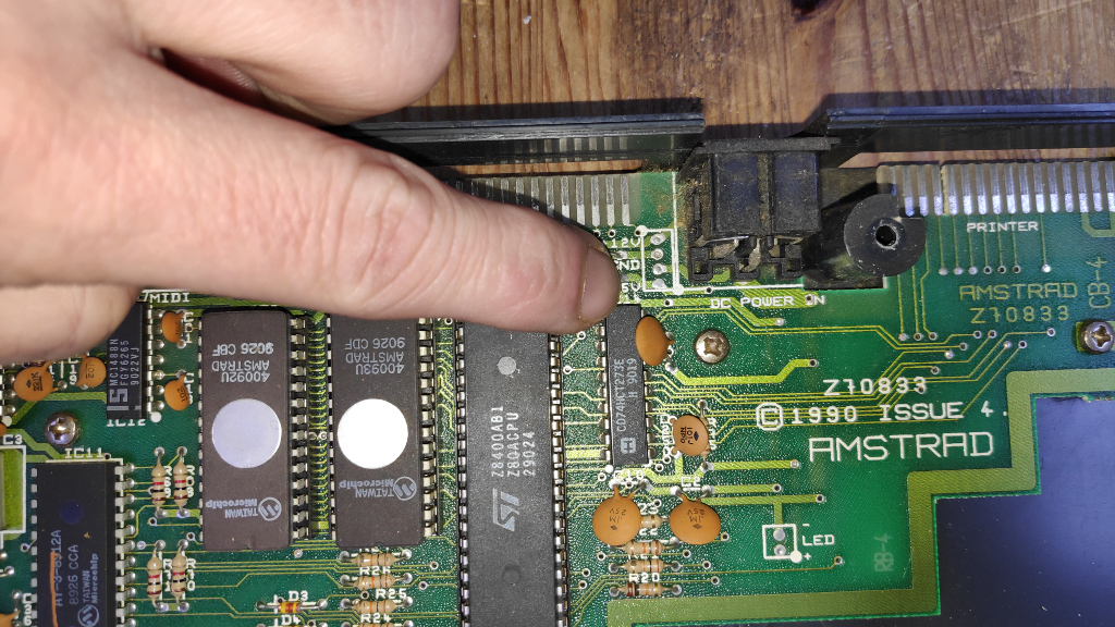
The solder method requires soldering these pins with the bend towards the back of the spectrum so as not to get in the way of the ide board when it is installed.
To solder these you will need to remove the motherboard which is held by 6 screws and just lifts out.
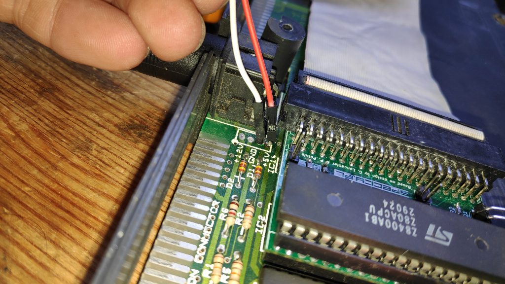
Photo shows the pins soldered and the ground (white) and 5v(red) leads connected. The leads just push on the pins.
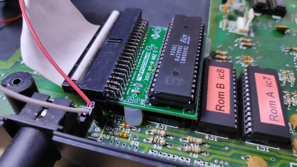
Next take the interface board and the Z80 CPU and install the CPU onto the board. Take note of the notch on the CPU and the notch on the CPU socket. These must aligned.
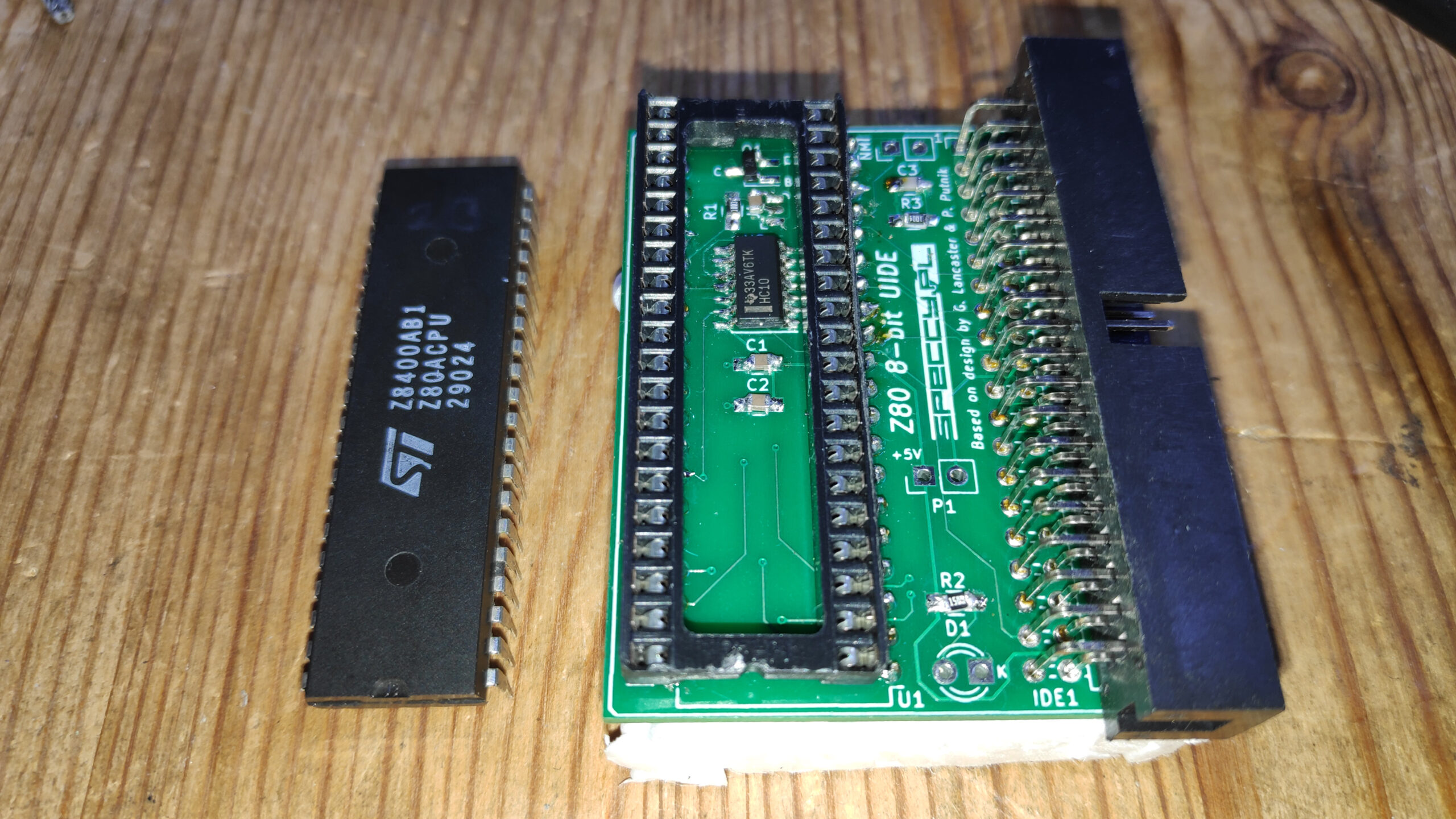
Connect the IDE cable to the interface and the IDE. Note the notch only allows the cable to be inserted correctly.
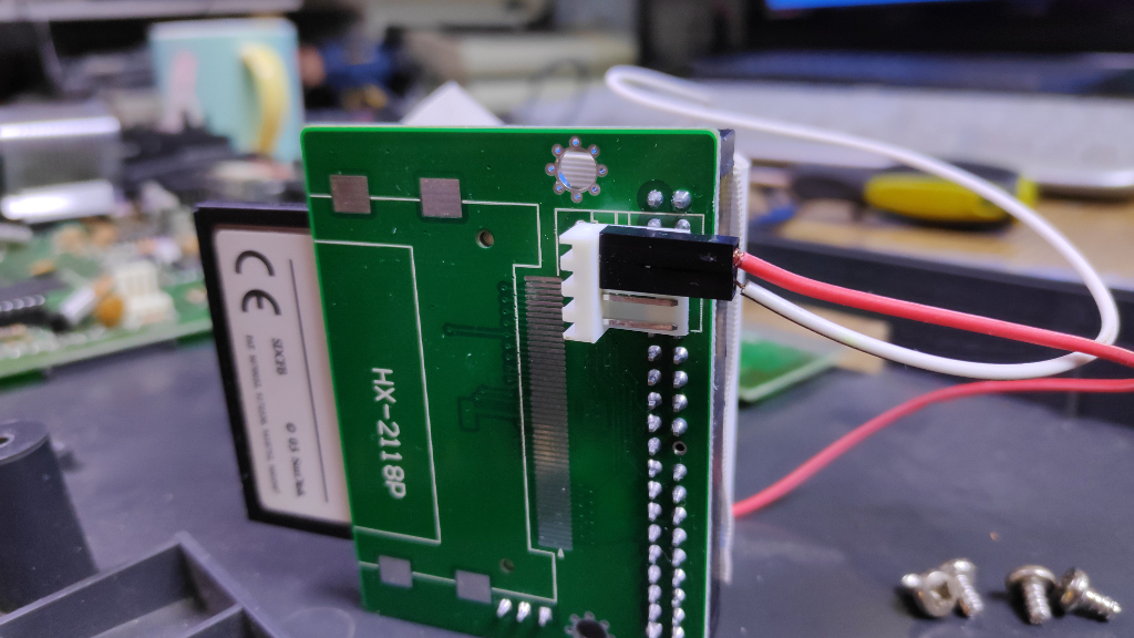
The ground and leads can be pushed onto the IDE card as shown. The 5v(Red) is on the top pin and the ground (white) on the next pin.
Install the interface into the CPU socket on the mother board making sure the pins align correctly into the socket. Press down firmly on the cpu to ensure the pins are fully inserted.
It is a good time to test the installation by connecting the keyboard and cables and turning on your spectrum. Be careful to lift the keyboard when turning on your spectrum so no keys are depressed otherwise it may go into test mode. You should see 1 IDE installed as shown
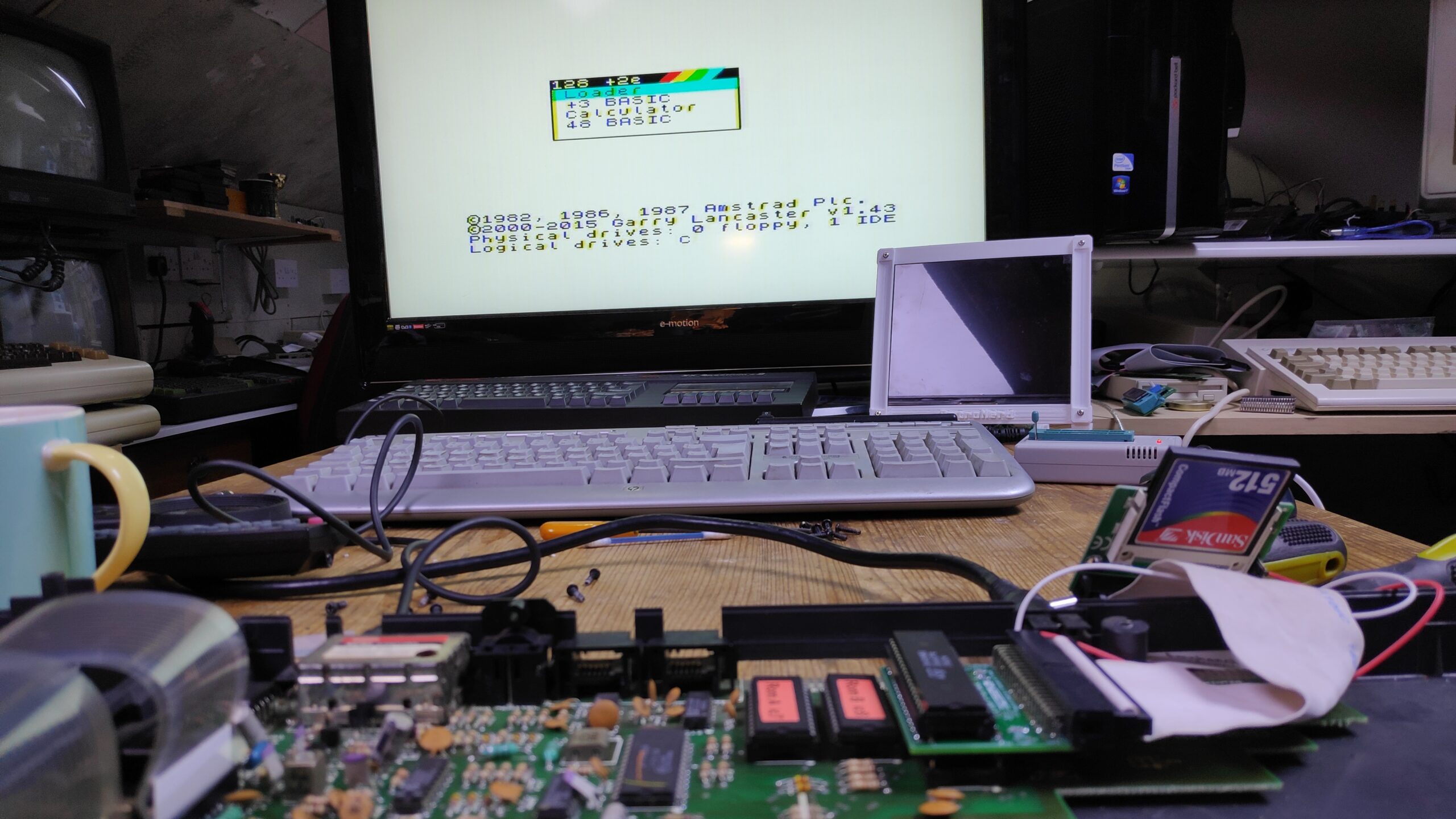
Select loader to test the menu appears.
Any issues at this stage could be due to the interface card pins not making full contact in the CPU socket , ROMS, IDE cable not fully installed, CPU pins not fully making contact in interface socket. Sometimes gently rocking the interface into the CPU socket is enough.
Once it is all working you can install the glue pegs provided which can be placed between the interface and the motherboard
The glue can be carefully melted using a hair dryer or heat gun. You can use a implement to smear the glue up onto the interface board. This will ensure the glue adheres on drying.
So you can close the case the IDE cable must be folded back on itself and then at 90 degrees so the compact flash card is in the space below the interface card as shown below.
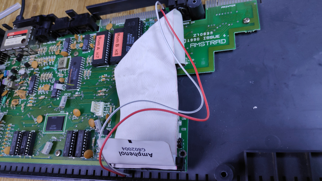
You can now reassemble and enjoy the fruits of your labour.
This is available as a preassembled kit to install
Available to buy here .