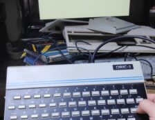
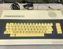
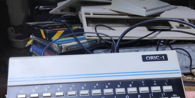
This Oric-1 repair story begins back in 1983. A time when everyone knows they are the flexible computer system for the future :).
The Oric-1 was the first computer I owned back in 1983 that I could actually use. There is an exception. I first owned, but couldn’t use!, a ZX Spectrum 16k for a couple of days which just kept resetting. This was replaced but the next Spectrum just did the same. I therefore traded the Spectrum for an Oric-1. The Oric was way more reliable and more importantly, usable!.
Unfortunately the Oric wasn’t quite as successful in the long run as the Spectrum but I have very fond memories of typing in long basic programs out of magazines and even wrote a bit of 6502 assembler. By the way If you could type on an Oric you could type on anything as they used tic tacs for keys :). With typical magazine games taking hours to input, your typing had to be good, otherwise it was another few frustrating hours finding typing mistakes. Unfortunately partly due to the tic tacs I spent many hours debugging but that was part of the fun and a great learning experience.
The Symptoms
So what about this Oric?. Well, It doesn’t work, hence the title :). It did however show signs of life as seen here.
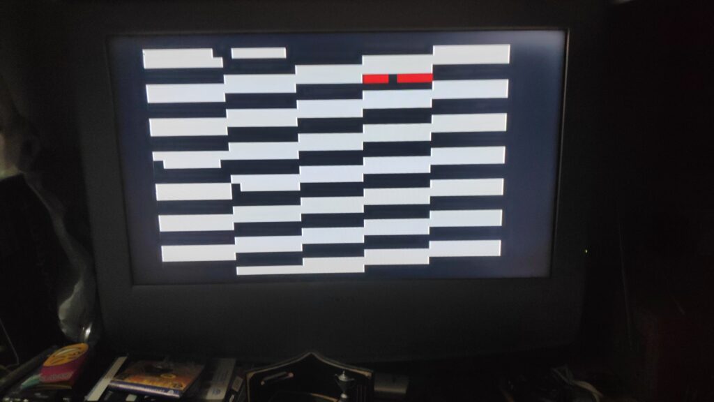
Pressing the keys should give a click from the speaker but got nothing just the usual hum from the speaker. FYI if you get a display then there is a good chance the ULA and clock signal are good so I was hopeful.
The Investigation
I did actually check the voltage on the PSU before booting the Oric which requires 9v from the center positive barrel plug. It was reading12v which I thought was high but then remembered the PSU is unregulated and not under load so 12v was acceptible.

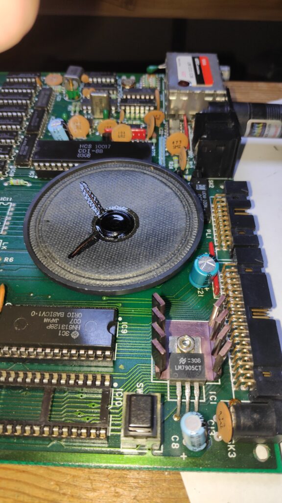
Next thing to check is the voltage regulator which is a unusual 7905 which takes in 9v from the supply and outputs -5v. This tested ok although it does run a little warm so onto the next checks.
A typical sign of failure is overheating chips. A simple test is to press the back of your finger to each chip but be careful as they can get really hot if they have failed. All the ram 4164 chips should be the same temperature so any running hotter is a good sign a chip has failed. Any other chips running really hot is another poetential point of failure. However all the chips in this case were just slightly warm but this isn’t a conclusive test so time to get the multimeter out.
There should be 4.9v to 5.0v on the 5v rail so measuring across any 74LSXX chip in the usual corners, e.g. pin 7/14 or 8/16 gave 5v which was a good sign.
Ram chips are a common point of failure on Orics so I measured GND pin 8 to pin 16 5V . All checked ok.
For this Oric-1 Repair I decided to make a Oric diagnostic rom with a spare 27SF256 I had just in case the rom had failed. The rom on the Oric is generally socketed so it was just a case of breaking out the TL866 programmer and programming the eeprom and swapping out the original rom. A slight change of screen.
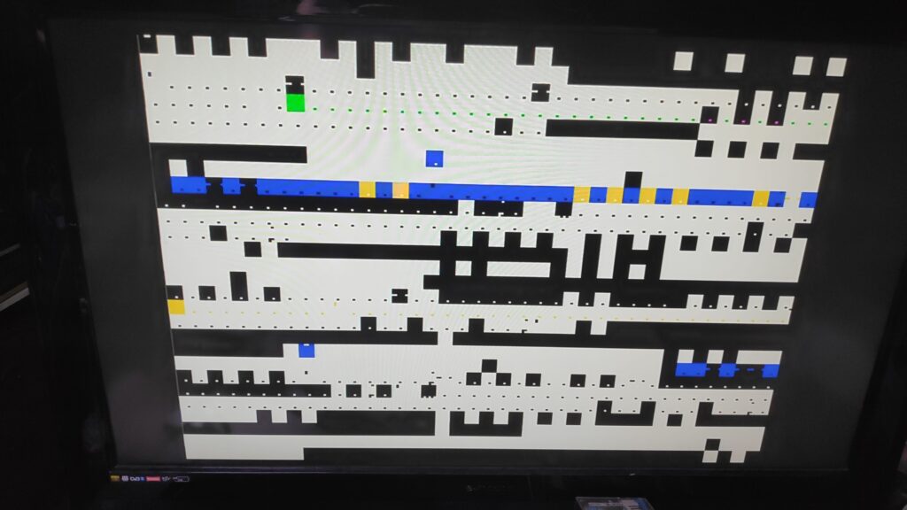
Still the reset button did nothing and the key presses produced no sound.
The Fix
Another common point of failure is the reset circuit. There is a reset button on the Oric but this did nothing in my case. A tip to check the reset circuit is to manually reset the CPU(6502). Using a wire or in my case metal tweezers momentarily short pin 1 to pin 40. Just a quick tap is enough. Please excuse the blurry photo as I was a bit nervous taking the photo while doing this. Yes the Oric was actually on, welcome to reality retro repair photo’s
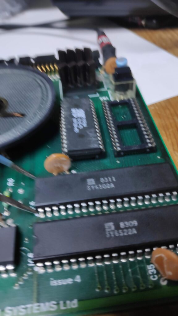
Look what happened.
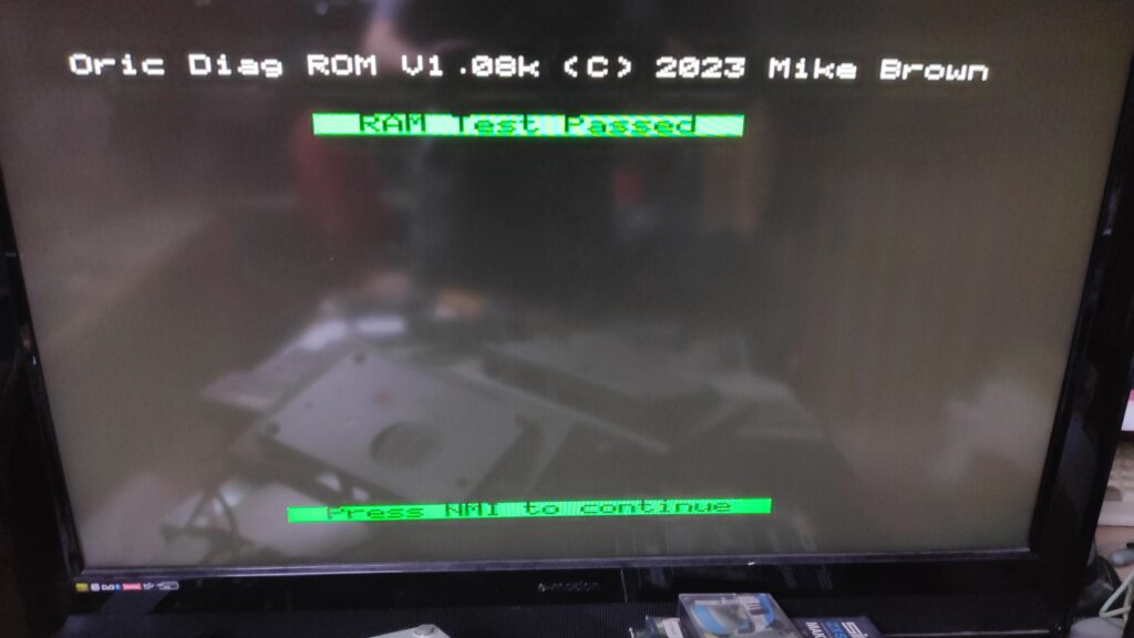
What a result. It sprung to life!. However a power cycle returned to the previous garbage screen. Fortunately manually resetting the CPU brought it back to life. By the way the reset button is the NMI and pressing it cycles through further tests. Unfortunately some of the tests need a test harness which I don’t have. Ram passed, 6522 passed, the processor must be working so things are looking up.
The reset circuit is primarily reliant on a capacitor C21 a 1uF 50v seen here hiding behind the speaker.
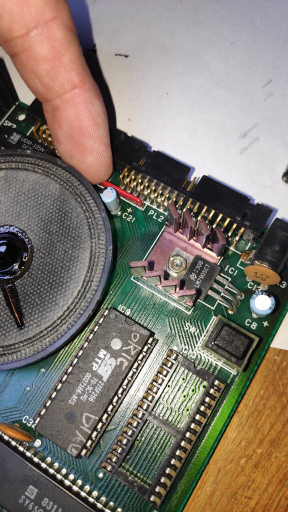
So it was out with the old and in with a new. However my research revealed that the reset circuit in the Oric wasn’t the most reliable. It can however be vastly improved by installing a 10uF 50V instead.
This solved it. The Oric now works perfectly.
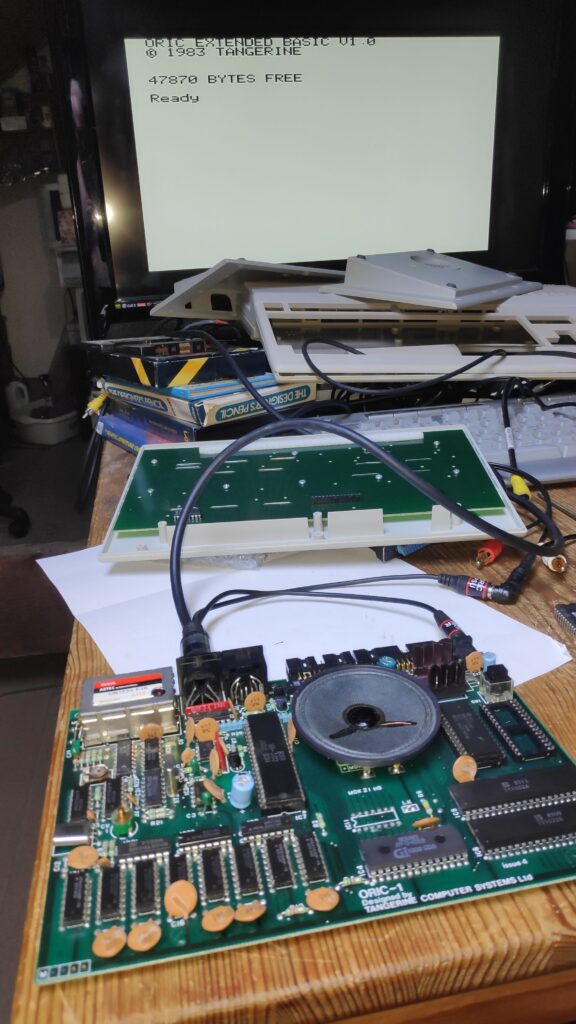
The Rom version is V1.0 which has a few bugs the worst of which is loading and saving from tape. The later rom versions fixed this. I managed to find V1.1 and programmed a eprom. Subsequently I found a newer V1.22 rom so I’m giving that a try. I’ll let you know how it goes but first issue is the double quotes and commercial at “,@ are switched round. I may modify the rom myself but hopefully someone has already done it.
I couldn’t find the corrected rom so just modified it myself. Final keyboard check before re-assembly.
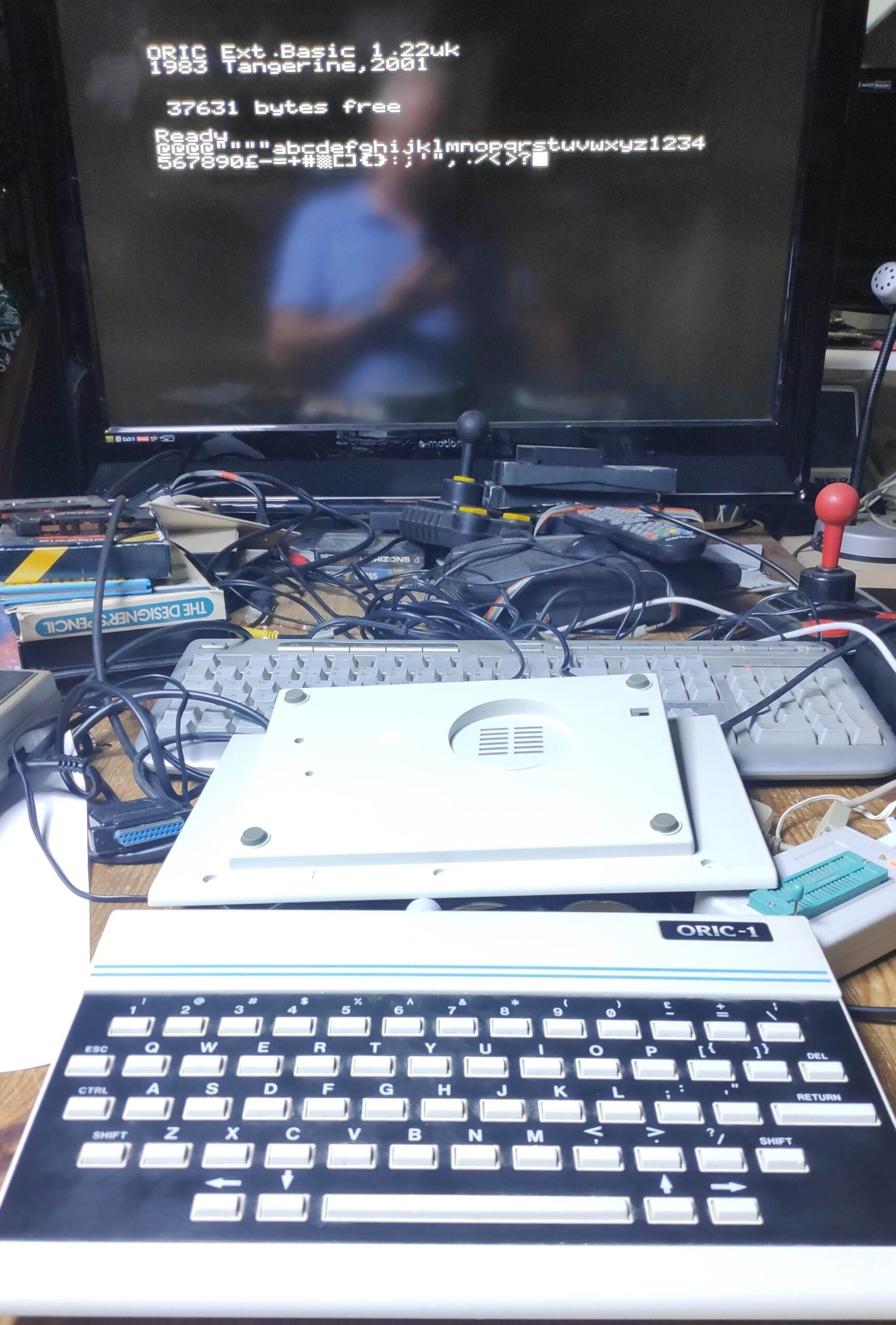
Make sure if your using a 32k eeproms like me 27SF256 or W2E257 that you program the rom file into the top half of the eeprom i.e from $4000 as address line 14 is always high.
Bonus
A bonus of the 10uF cap is the usual hum from the speaker is drastically reduced. I decided to apply this to my other Oric and low and behold before actually doing the mod it wouldn’t boot. Shocker!. However it turned out to be the same issue so that was a relief!.
Took the time to replace the other electrolytic 100uF and 220uF caps and the 7905 Voltage reg. The speaker hum is further reduced and the heat is reduced from the VR.
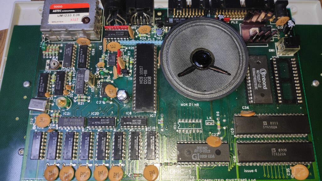
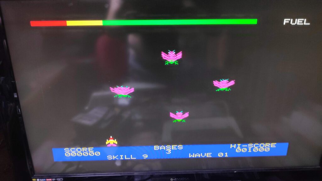
Just need to put it back together and play a few games. Xenon anyone ?
Caveat
I’ve since found a problem using eeproms. Disk drives, erebus, microdisc etc. dont work. This is due to the ROMDIS signal not being compatible with most eproms. There is a fix to bend the chip enable pin out so it doesn’t go into the socket and solder a wire from CE pin 20 to pin 1 GND. The issue now is the Erebus Floppy disk interface needs to be connected for the Oric to boot.
Eproms that supposedly work without mod , HITACHI models HN2764 and HN27128. Possibly the MITSUBISHI model M5L2764K. I don’t have these so can’t check.
I’m working on a more elegant solution to this so watch this space.
Finally to end this post I’ve sorted the ROMDIS signal compatibility issue with an adapter board as shown.
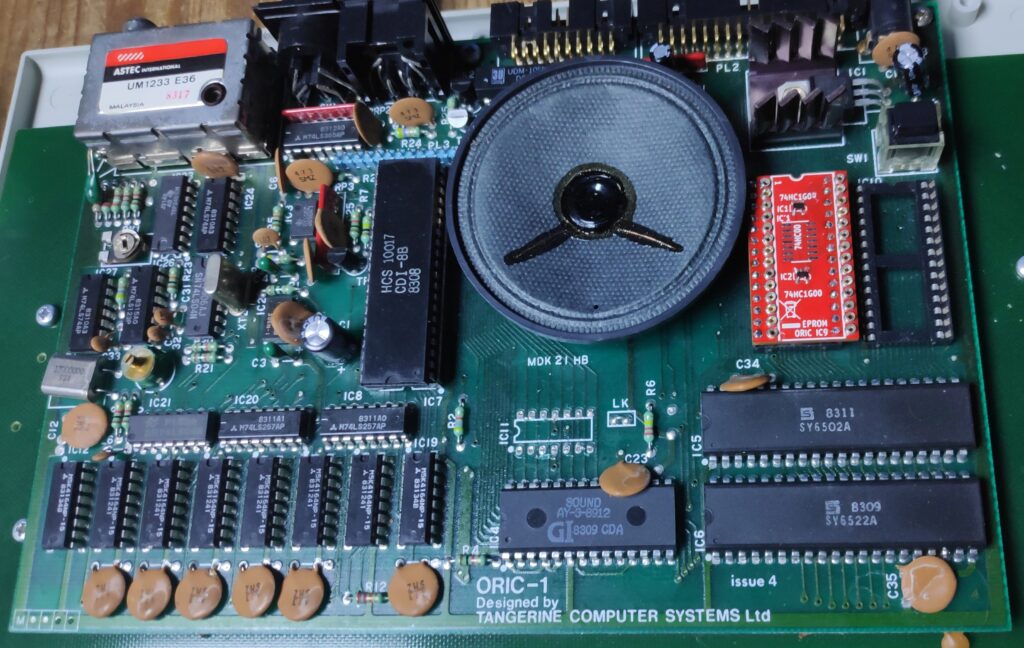
And a custom programmed W27E257 eprom now works perfectly with the EREBUS drive.
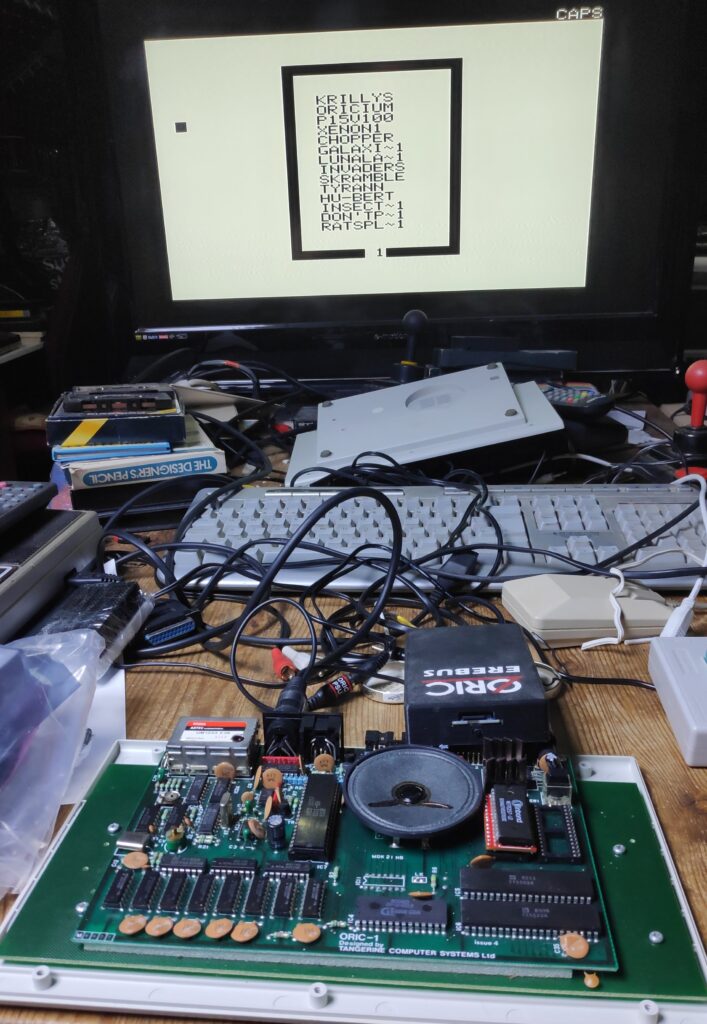
If anyone is interested in one of these ROM adapters just send me a message here. I’ve used narrow 0.4mm pins to relieve any stress on the precious original Oric rom socket.

