


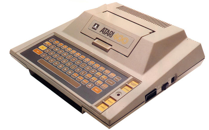


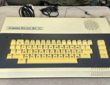

Atari 1020 Colour Printer Plotter Repair. This printer plotter is an Alps design which was reused for the Commodore 1520 plotter the MSX PRN-C41 and Oric MCP-40 amongst others.
This Atari 1020 is another Ebay untested purchase so no surprise it didn’t work when I tested it. But thats ok as its more fun for me 🙂
Symptoms
The good news is the power supply is working giving a healthy 9v ac and the SIO cable tests ok with my floppy drive.
So by process of elimination its the Plotter itself which is faulty. Let the fun begin.
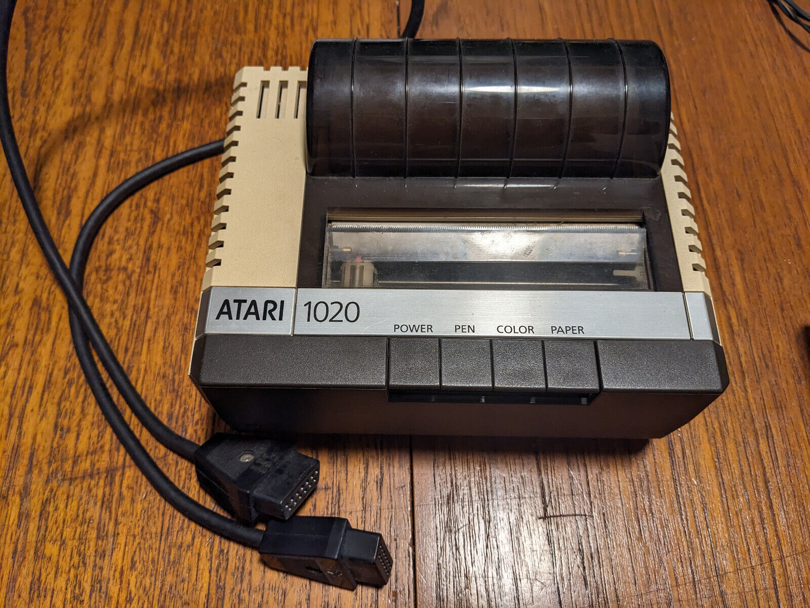
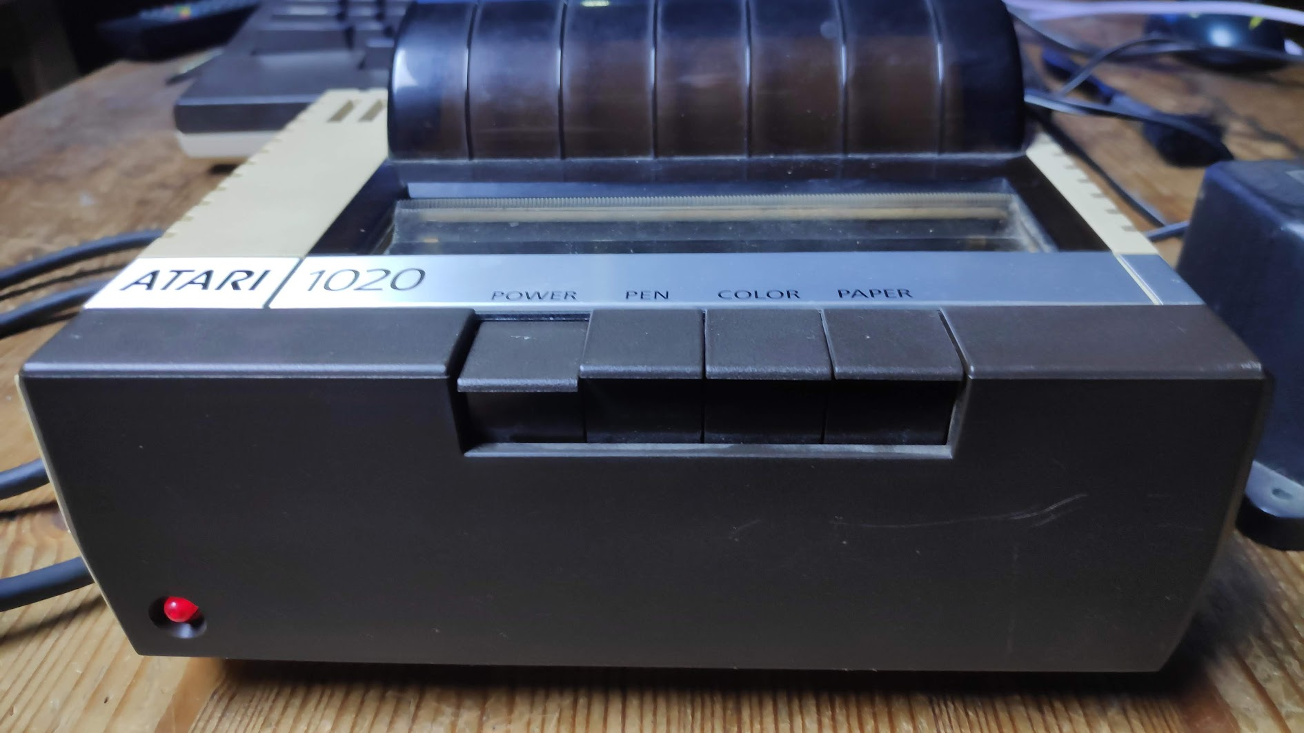
The symptoms on switch on are no activity from the print head or paper roller. The red led lights up ok so there is power going into the unit. When first turned on the unit should go through its initialisation procedure by moving the print head back and forth and moving the paper roller. Then it should print 4 small squares with each colour.
Case Disassembly
Disassembly starts by removing the top paper cover which just slides back a little then lifts off. Remove any paper by gently pilling it out. Turn the unit upside down to reveal the 3 screws on the bottom of the unit. Remove the screws.
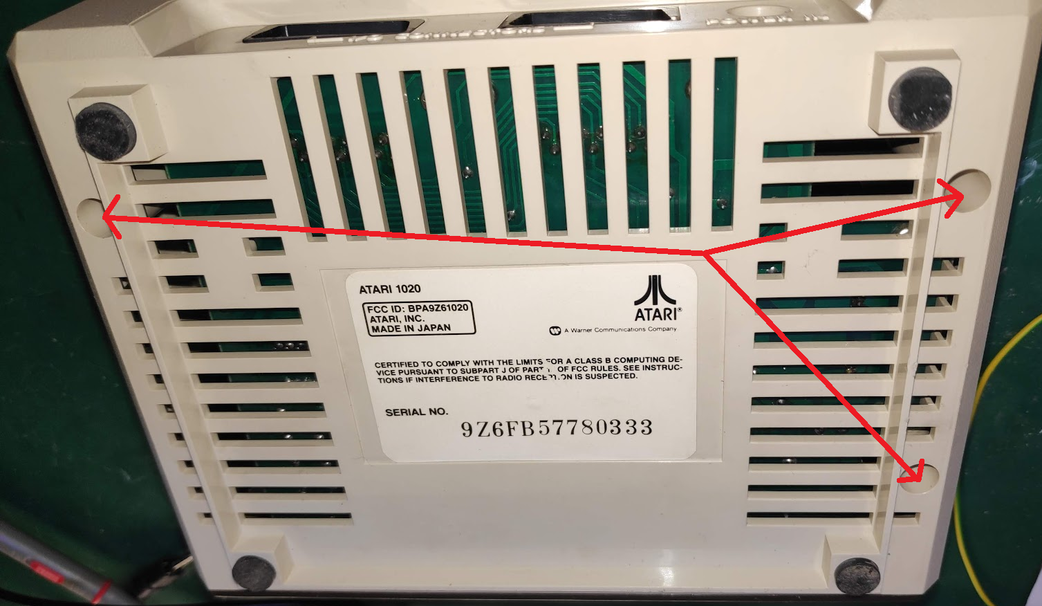
Next remove the two front rubber feet to reveal two more screws.
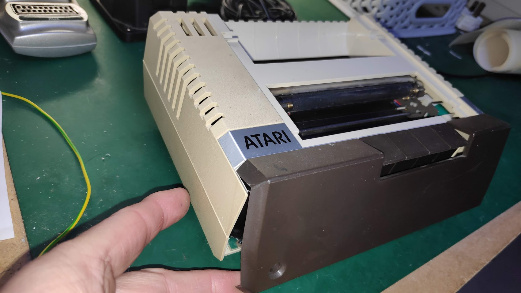
Next remove the front brown panel by gently separating it at the bottom from the beige case and a little bit of lift. There will be some resistance so be careful and just keep working it until it lifts off the two hinges. One is visible and the other hidden. You can see the hinges in the second image below. You may need to gently flex the the brown cover to remove it.
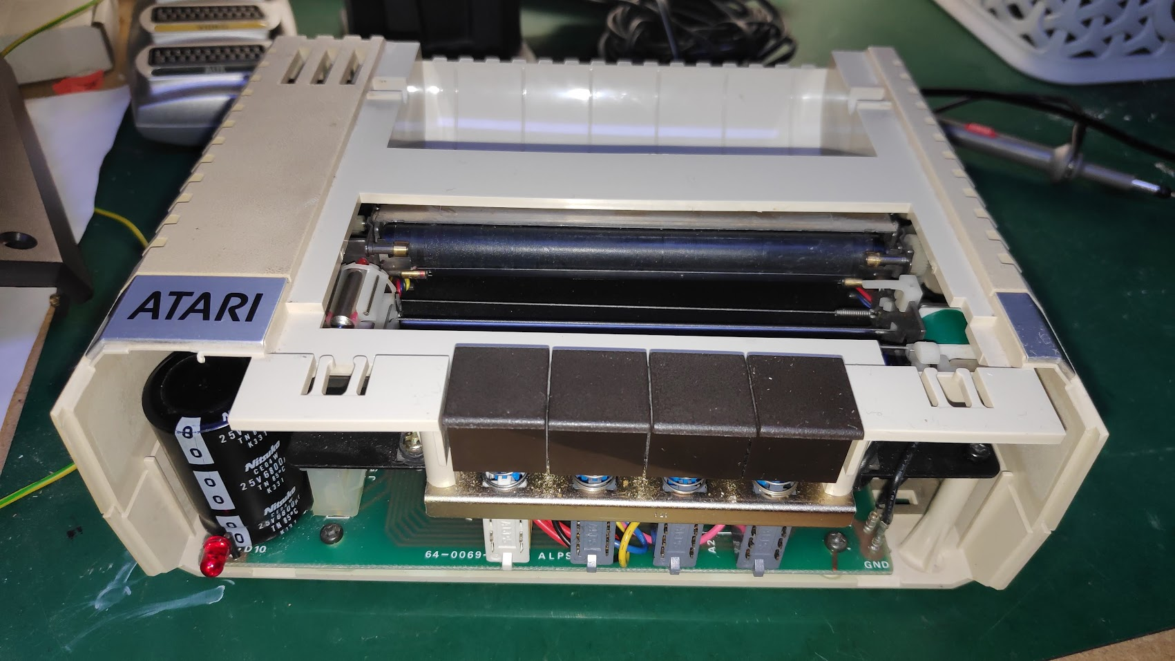
The case can now be carefully reparated but be careful as the buttons are attached to the top half and the circuit board on the bottom half. It opens like a clam shell as below.
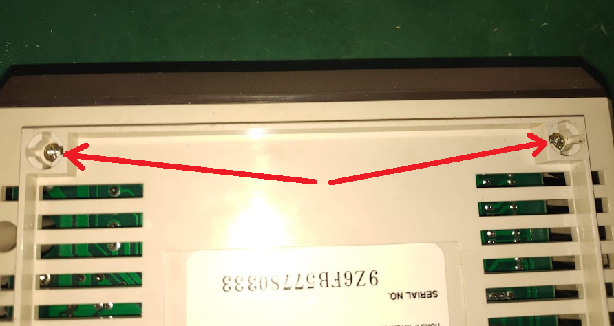
The two screws marked can be removed to seperate the buttons and allow the top case to be removed.
Mechanism and Circuit Board Dissasembly
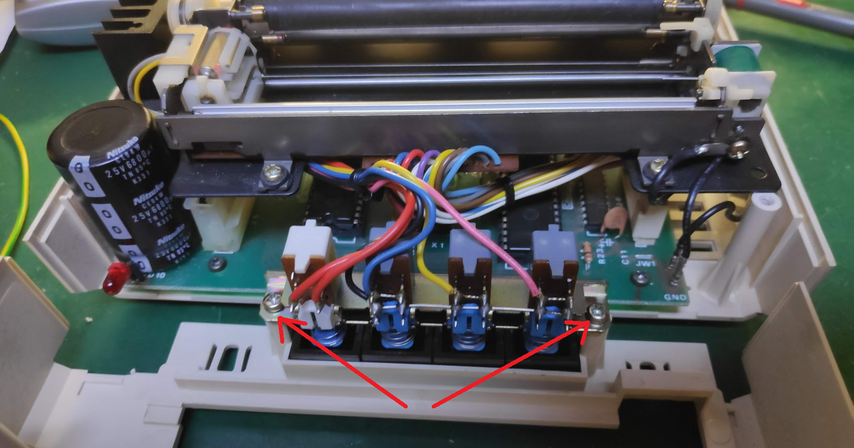
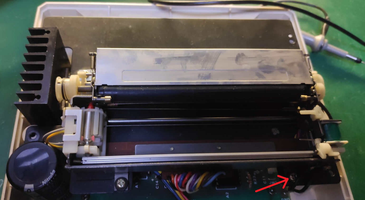
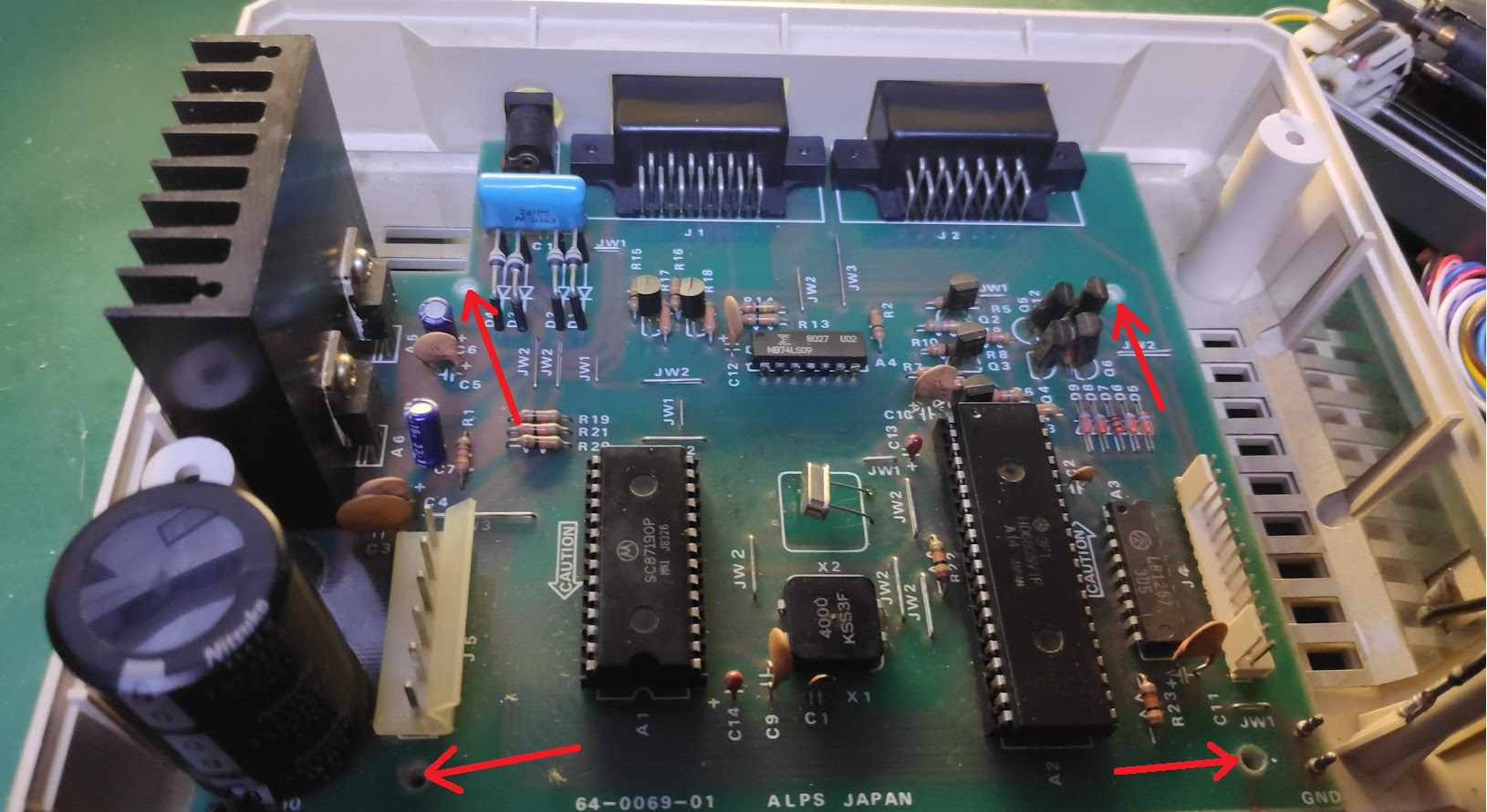
Next the mechanical section can be separated by removing one screw marked in red below disconnecting the two black wires by pulling them off the circuit board as shown below. Be advised the print mechanism connects to the circuit board with a ribbon cable which can be removed by lifting the mechanism and removing the connector.
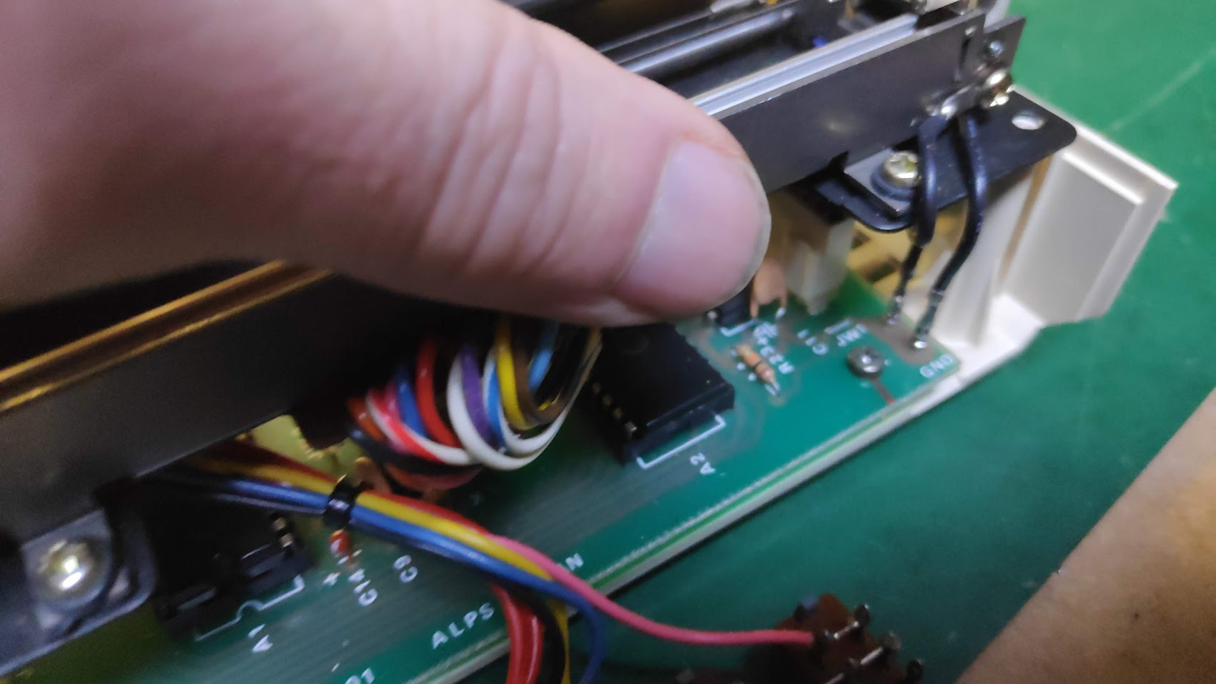
The print mechanism connects to the circuit board as below. Remove the connector by holding the plastic NOT! the wires. Its easier the rock the plastic connector with finger and thumb to get it started then it should slide off.
The buttons can now be removed by pressing the clamp connector plastic away from the plug and pulling on the plug by holding the plastic NOT! the wires. Its easier the rock the plastic connector with finger and thumb to get it started then it should slide off.
The circuit board can now be removed by first removing the four screws. Shown removed here
Inspection and Testing
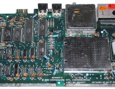
With the circuit board removed you can inspect it for any corrosion or burn marks.
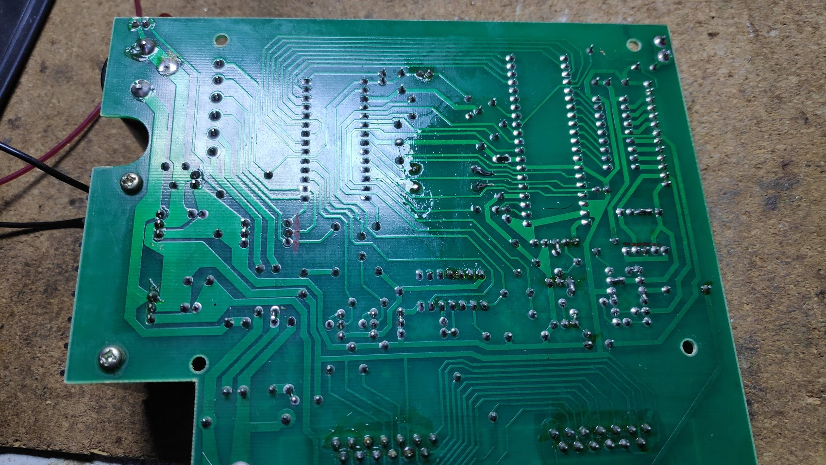
No burn marks here only some flux residue. I reflowed the solder on some of the suspect looking joints. Unfortunately this didn’t fix anything.
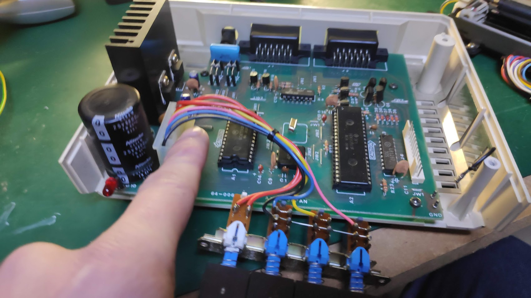
Cleaned and inspected the board for any bulging capacitors or burnt components.
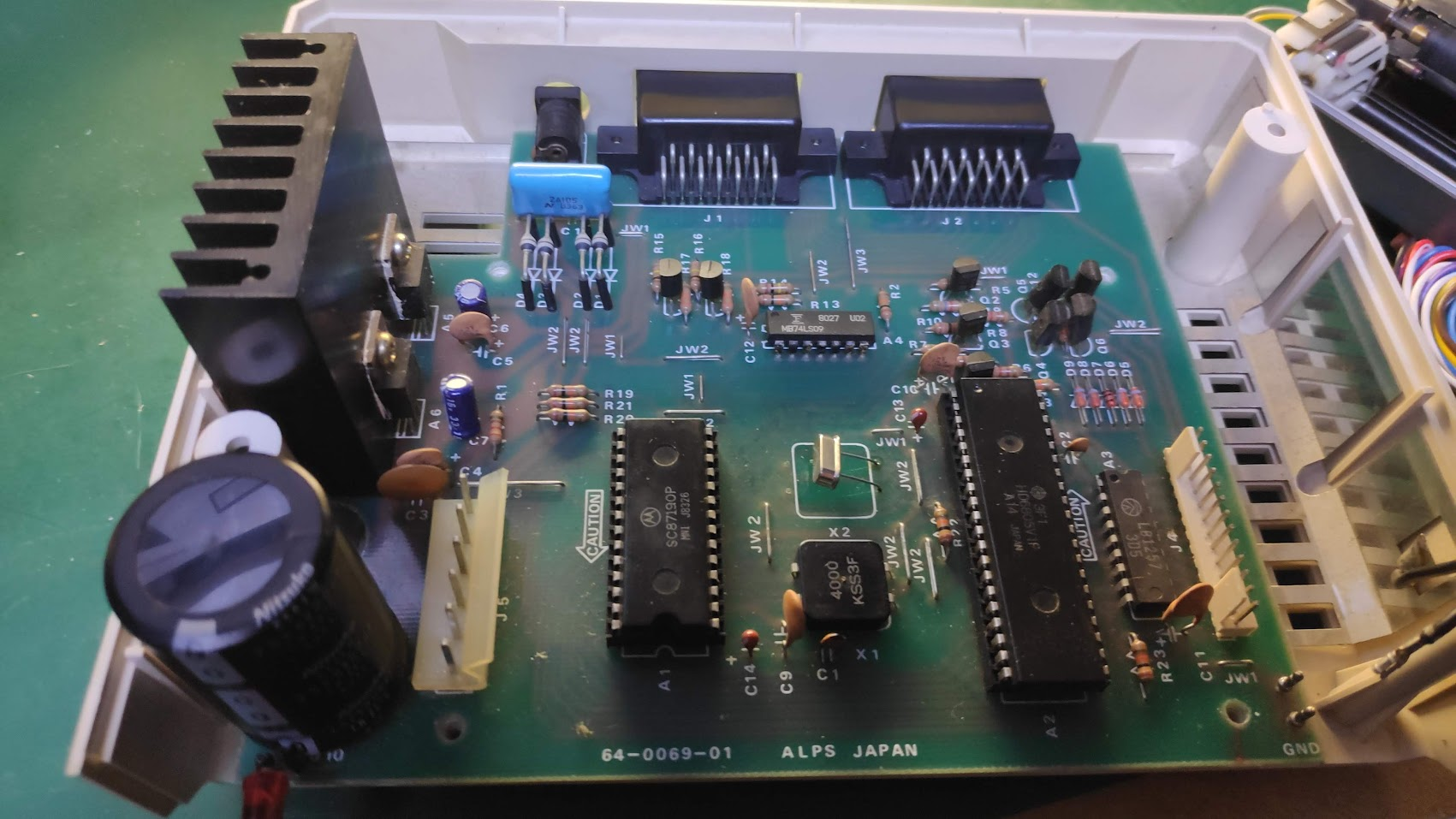
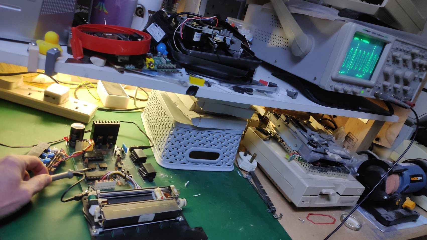
Everything looks ok so the parts can be easily reconnected outside of the case for further testing.
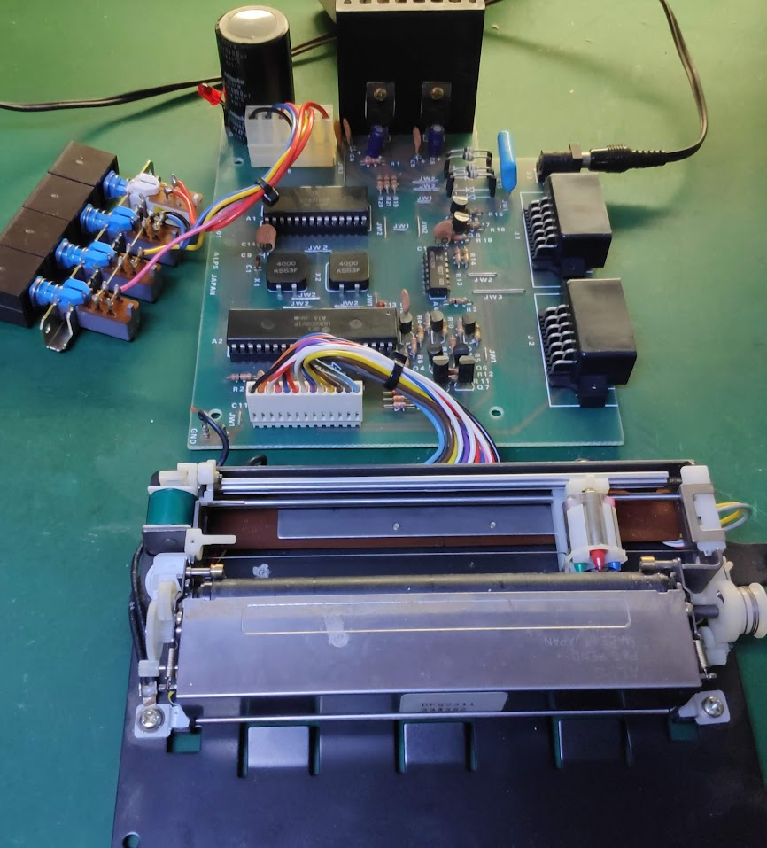
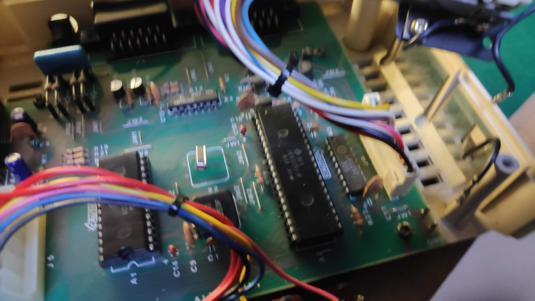
The largest chip is the microcontroller with the following pin configuration.
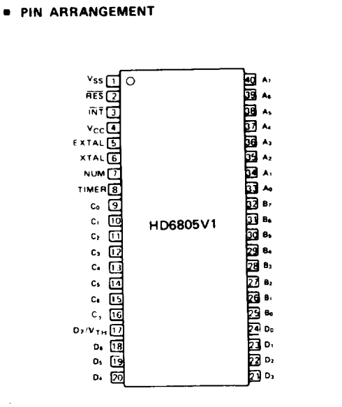
With the power switched I tested pin 1 top left of the microcontroller chip with a multimeter on voltage . This showed a nominal 5 volts as did the other chips.
I also tested the supply supply voltages on the other chips which all had 5v supply.
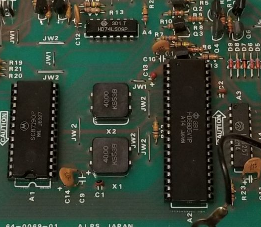
The A1 SC87190P chip also showed 5v. The 74LS09 chip (A4) pin 14 showed 5v. I decided to check the clock signals from the two 4000 KSS3B chips X1 and X2.
The first one checked out ok.
The second however showed nothing
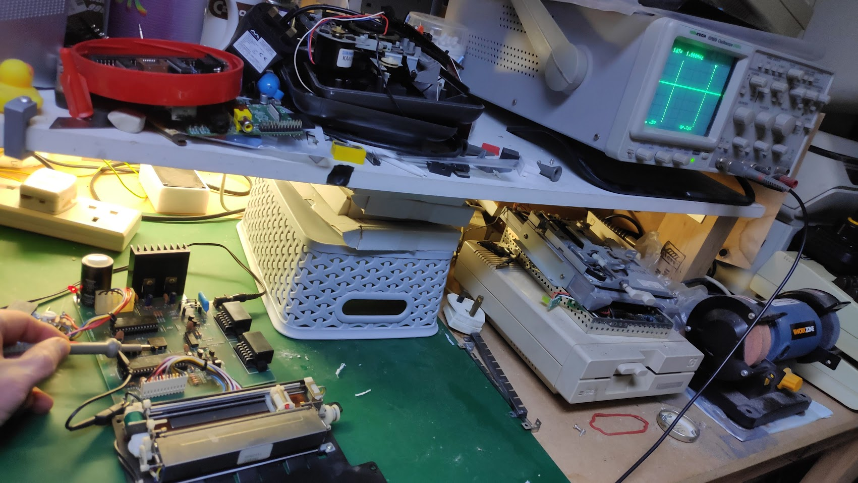
This supplies the main microncontroller chip with a clock so nothing will work without it hence the mechanism inactivity. So it was either the chip or the clock. I orderd a 4Mhz crystal as they are readily available. I did manage to source a HD6805V1P A14 chip just in case.
Solution
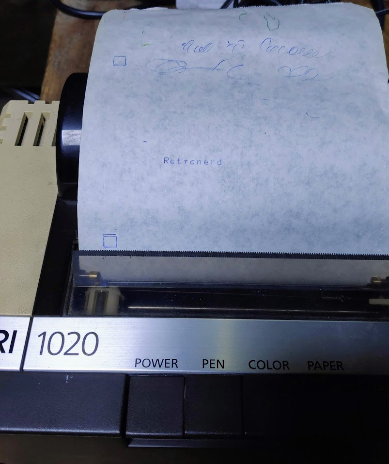
Swapping out the X2 crystal and…
Asuccessful Atari 1020 Colour Printer Plotter Repair.
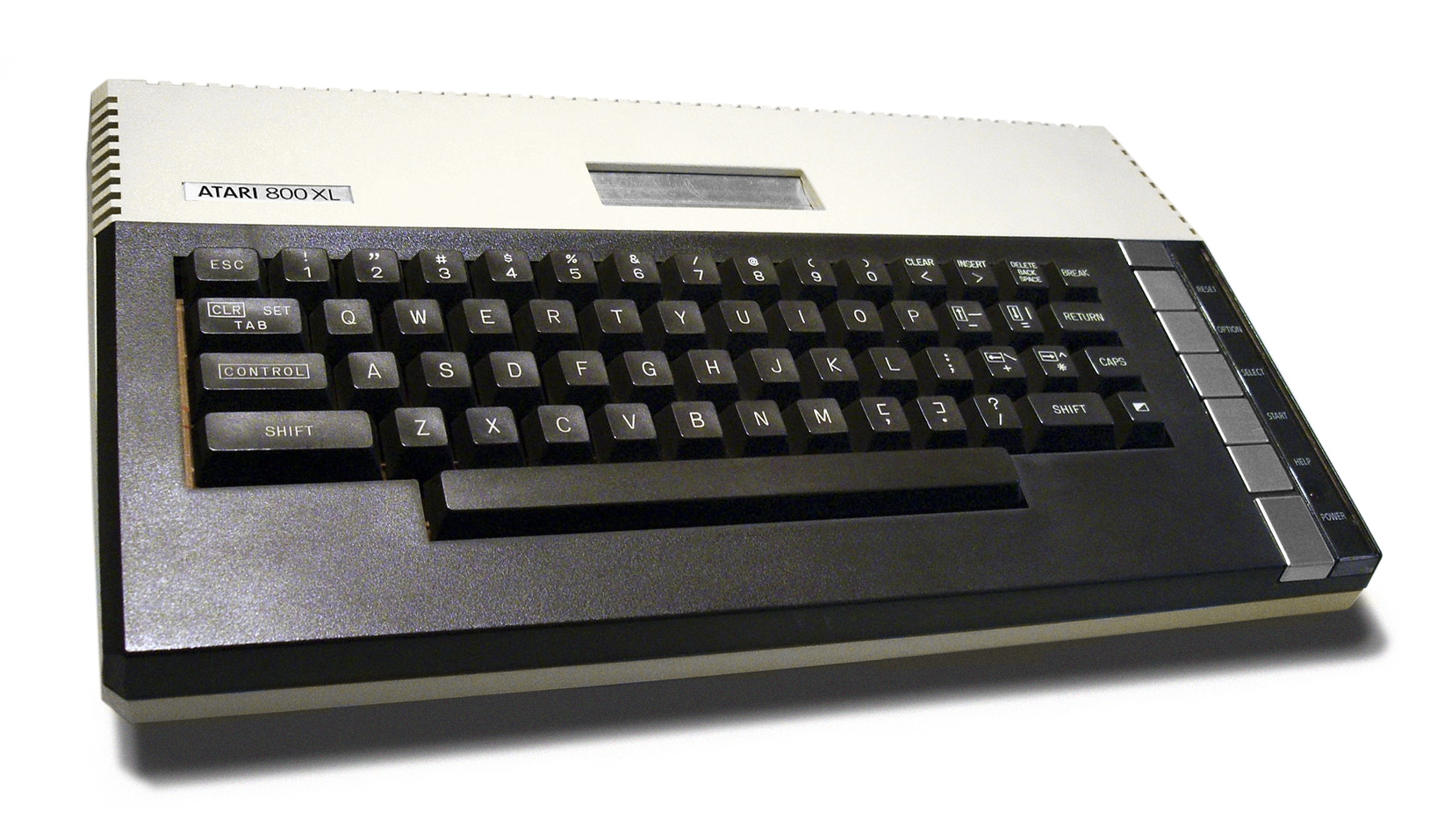
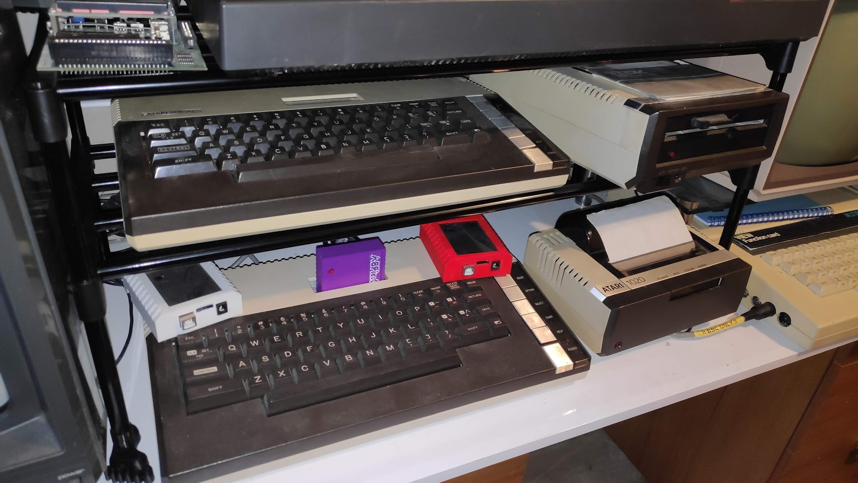
Reassembly is just the reverse of disassembly. With things back together its a nice addition to my Atari XL setup but a new issue has emerged.
The pens have dried up.
I’m trying a reydration process which supposedly rehydrates the dried up internal fibres in the nib. The process involves boiling water and placing the pen in the water. Any air is supposed to leak and bubbles emerge from the plastic seal. Then as the water cools its drawn back into the pen thereby rehydrating. I’ll post back later with results.
Ok so the results are in for two of the pens. I tried the green pen first and let it soak in boiled water just up to below the tip but above the metal casing as shown.
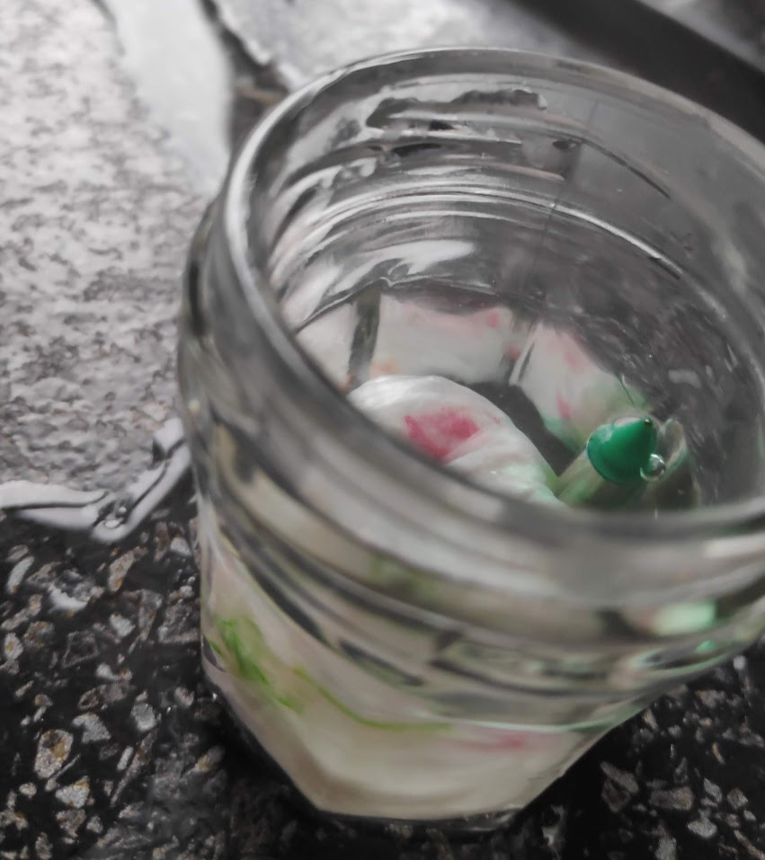
This was allowed to then cool to room temperature. The tissue in the bottom was to keep the pen upright. This was a bust and also a bit of the gren ink leaked. I tried exactly the same with the blue pen and got this.
I’ll continue with the other red and blue pens I have and report back soon.


