
This was purchased from a family whose father had used the QL for his business in the 1980’s. The computer quickly outlived its usefullness and, as many Sinclair QL’s before it, was then stored in the loft and left unused for decades.
The sale was described as turns on but unable to test. I didn’t hold out much hope. However I liked the condition of the box and the the unit so thought I’d take the risk. Worst case it would make a nice addition to my retro wall if I couldn’t get it working.
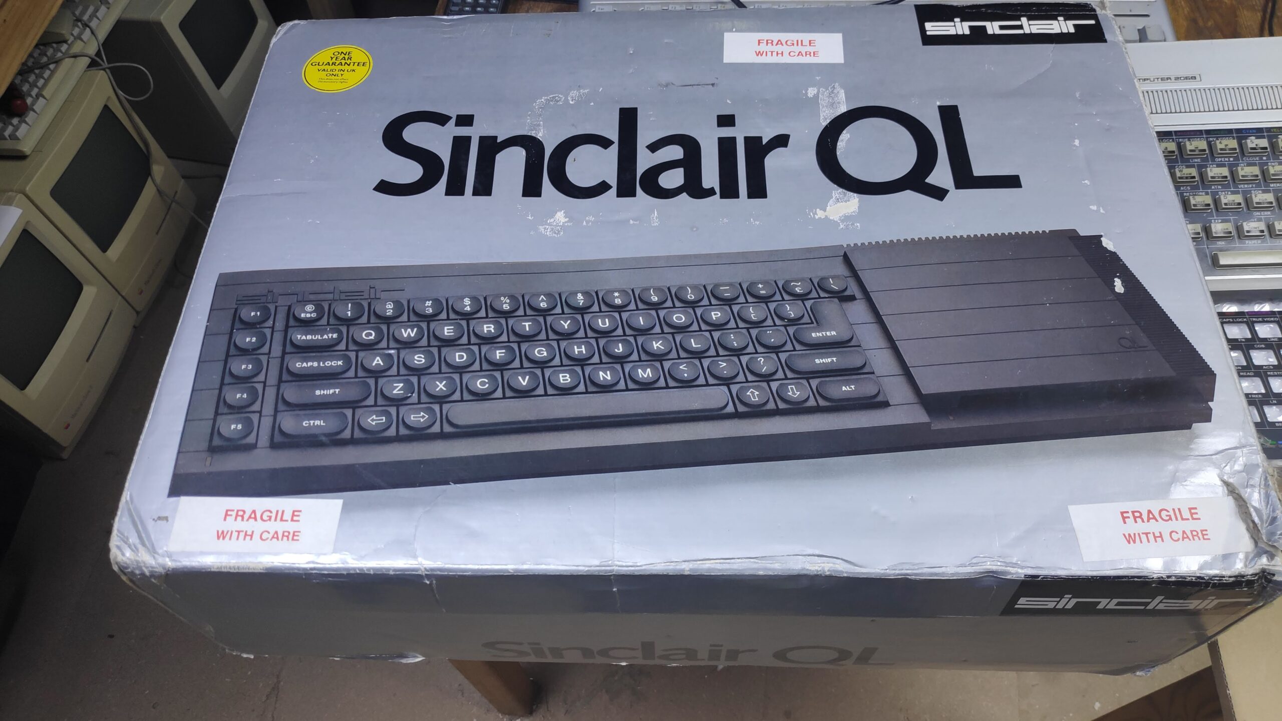
First things first – The Unboxing
The box was in good condition and it came with the polys albeit a little damaged but maybe the polys can be repaired but thats a project for later.
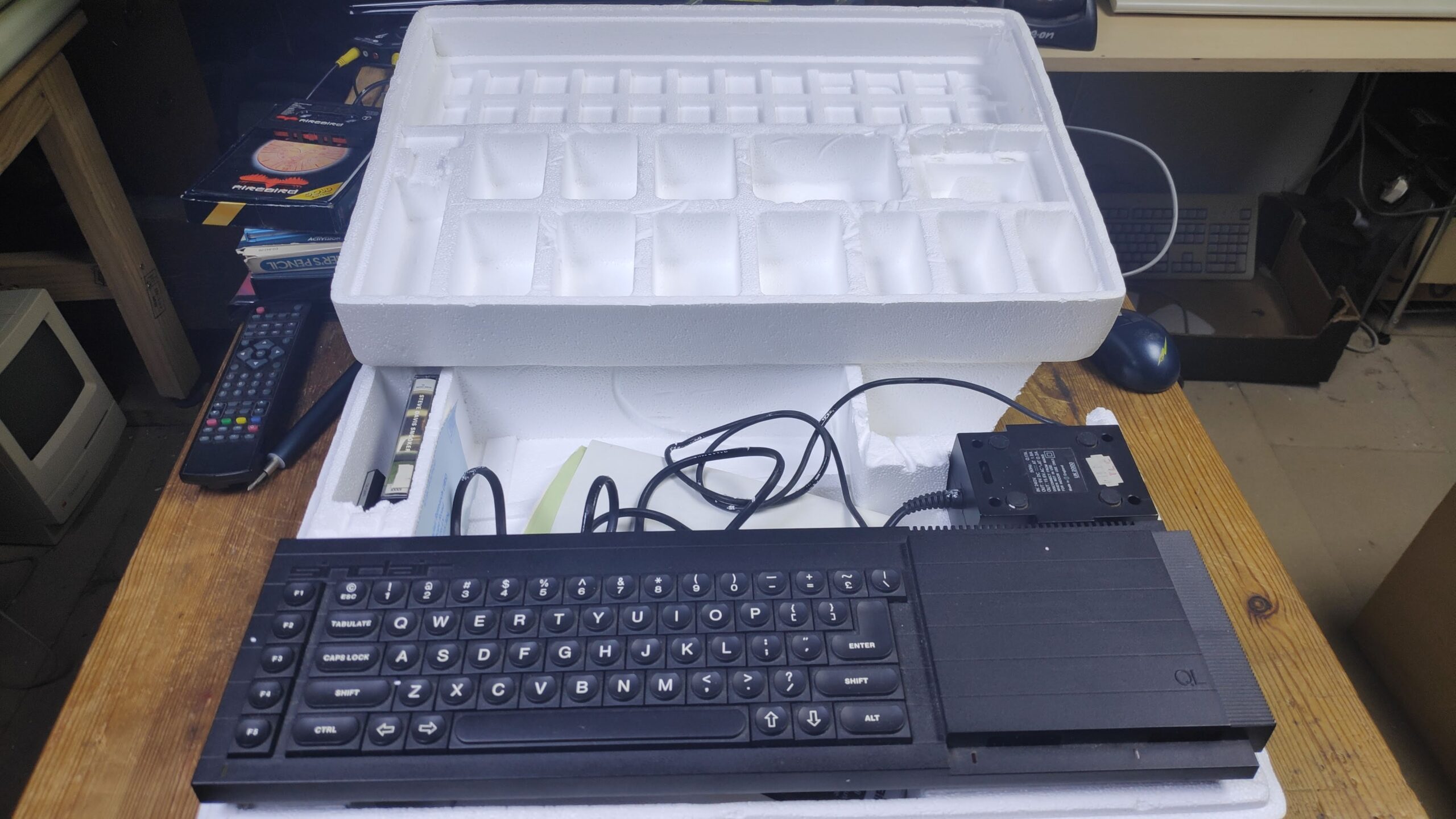
I was glad the power supply was included as they are very hard to find and there was a few microdrive cartridges. What was surprising was the old documentation which on occsasion can be included and makes a nice read.
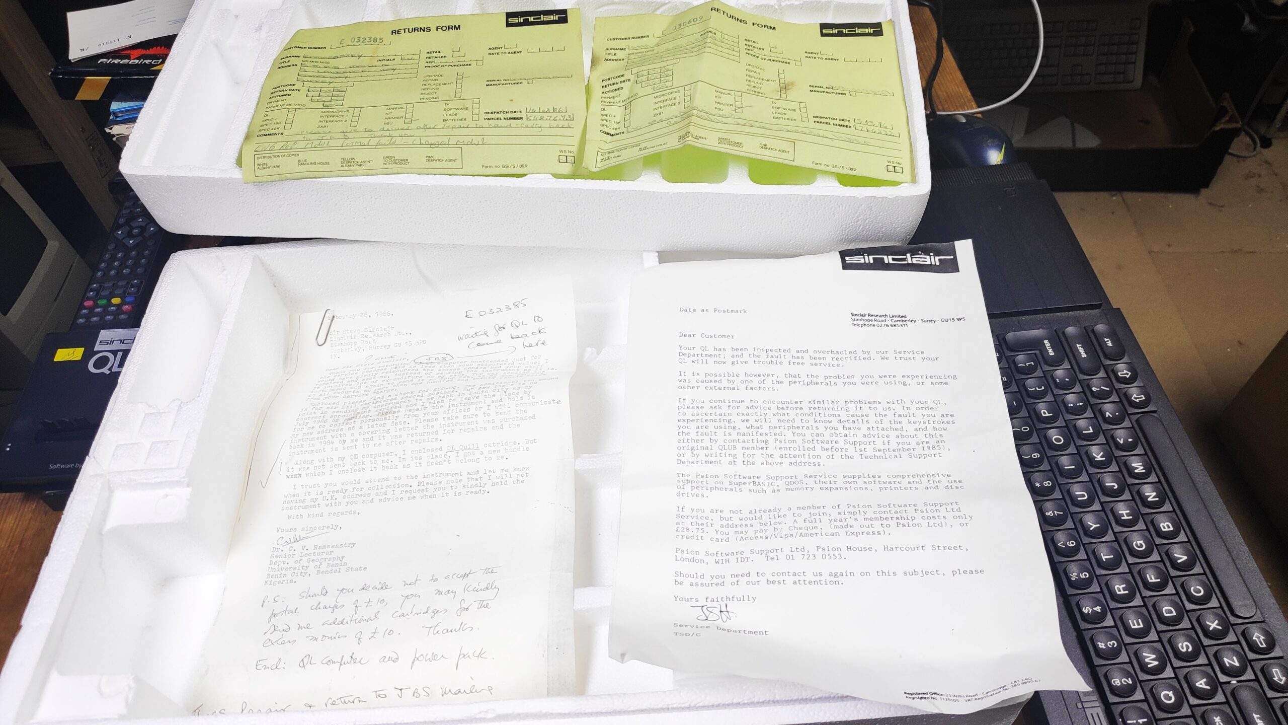
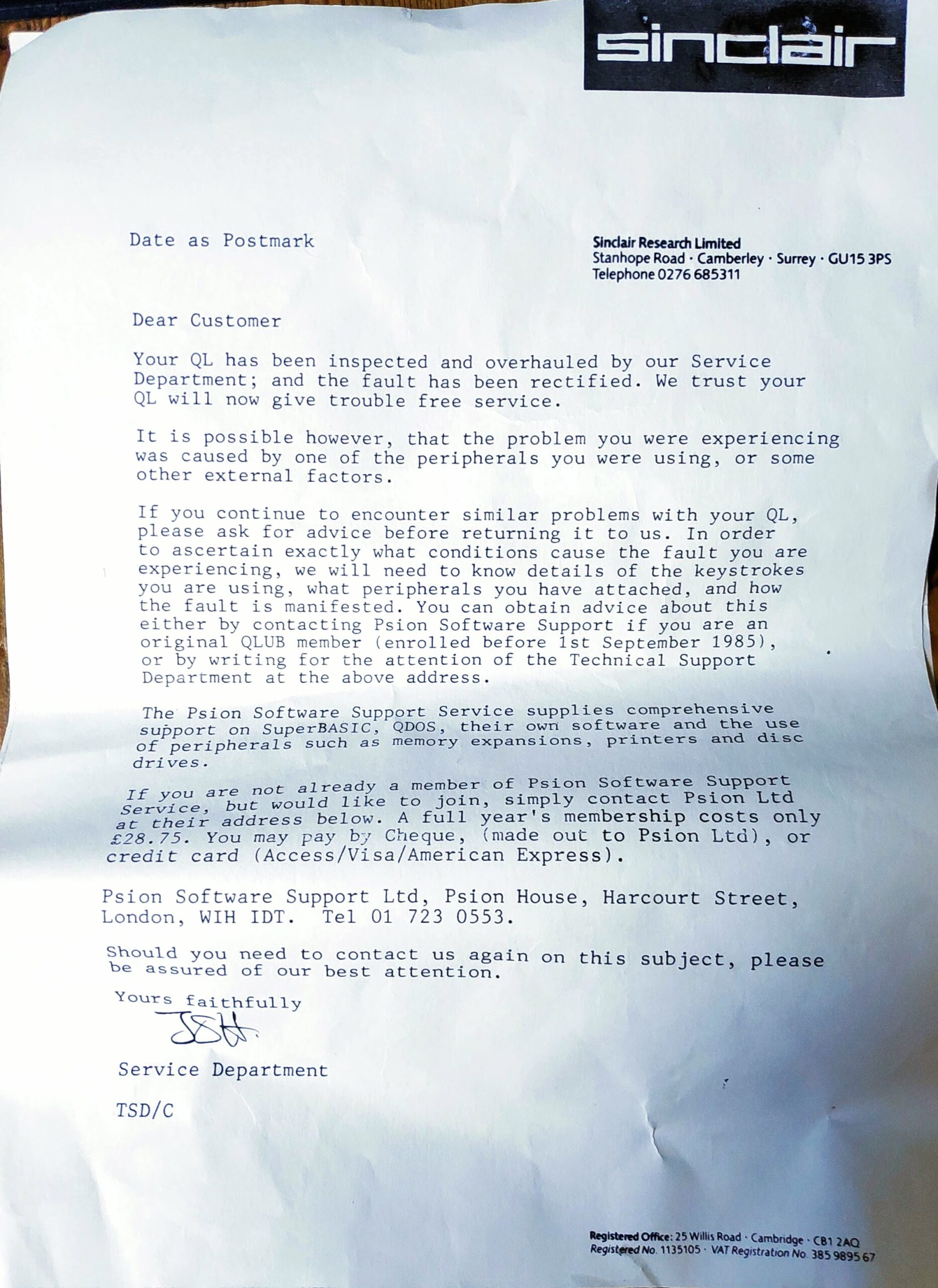
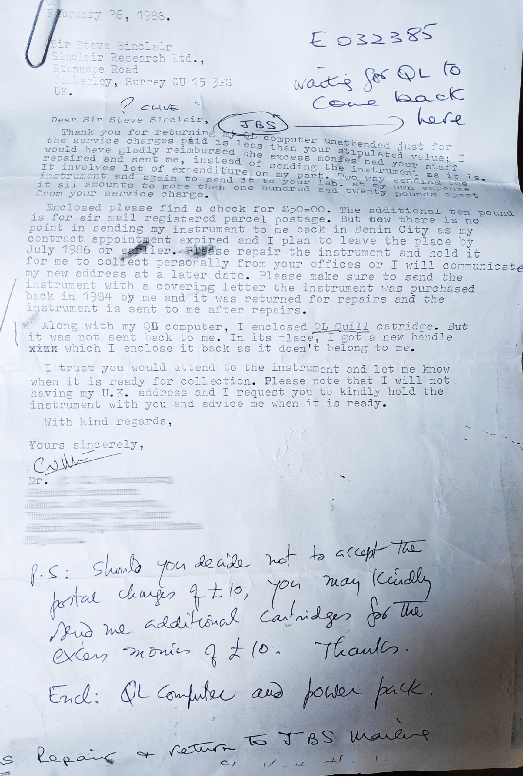
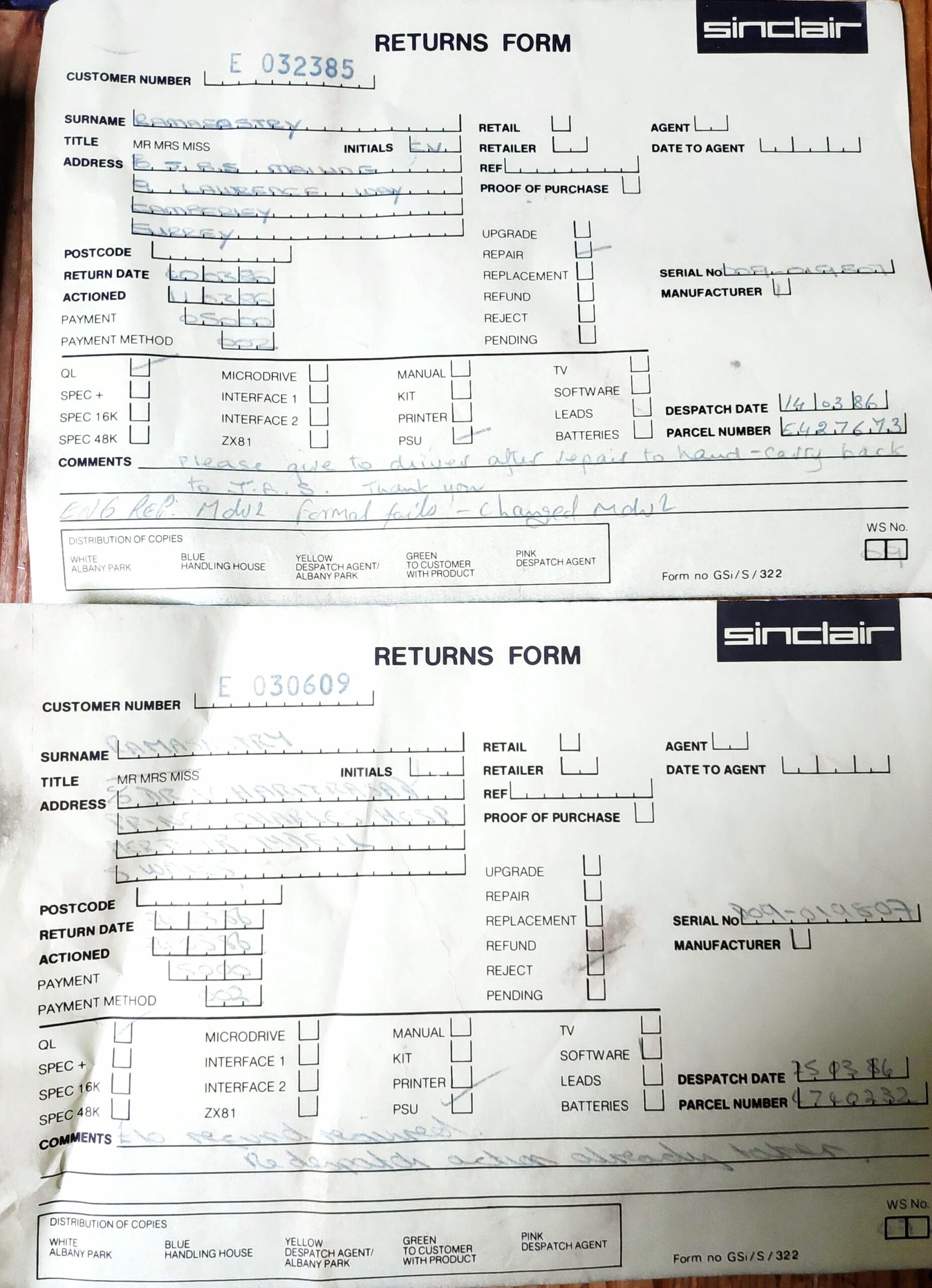
Looks like there was an issue with the microdrive and once repaired they misplaced his catridges. Then there was still an issue loading. Hopefully the issues were resolved back in 1986.
During purchase I witnessed the unit turned on but without a TV conneted. The power light was on and the microdrive did start up so I was hopeful it was working still a risk however.
Once back at the man cave I thought I would briefly power on the unit while connected to a TV. Initially I got this.
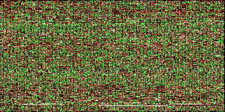
However after a few power cycles I got this.
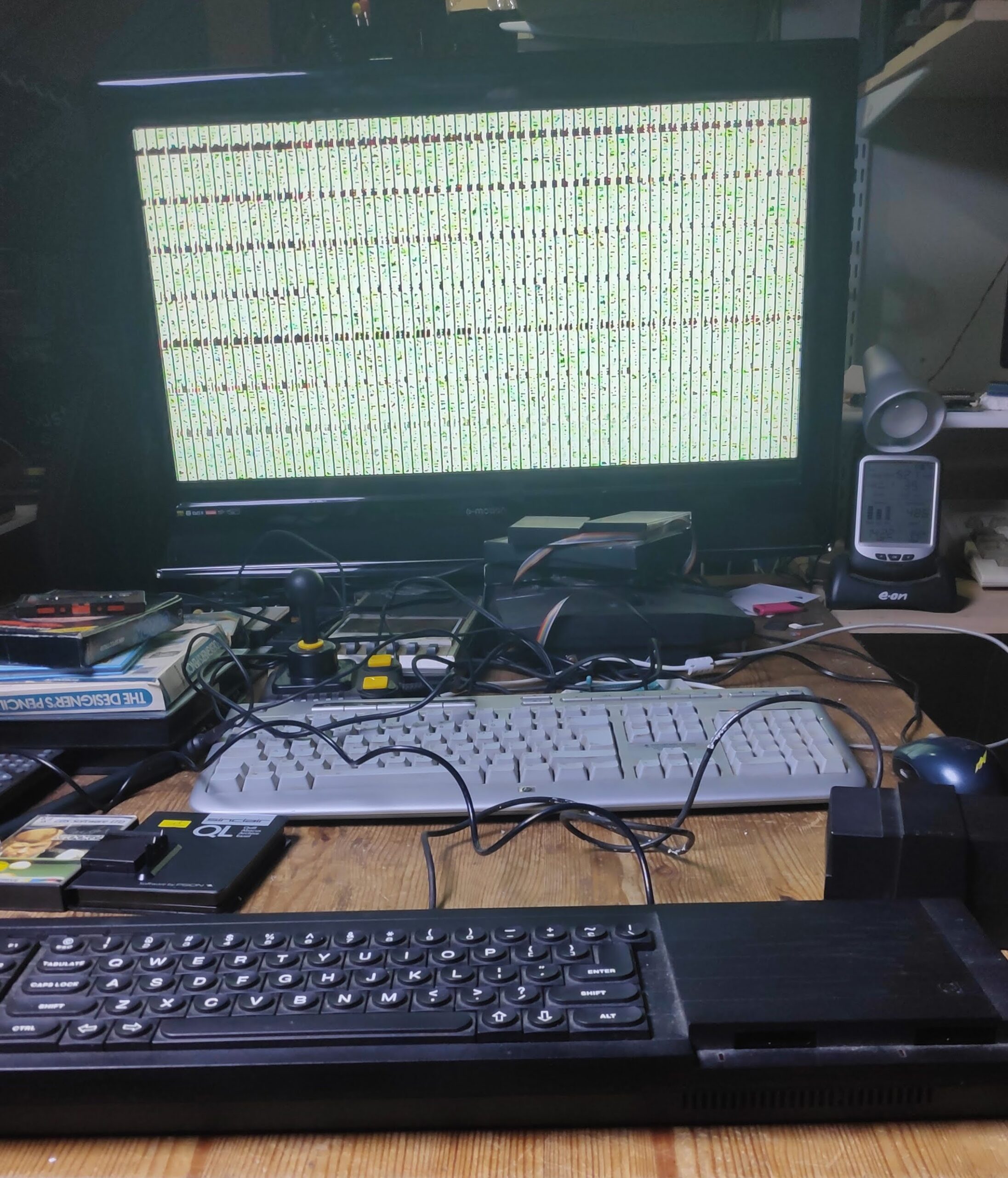
So all was not well but at least I was getting something displayed and the microdrive started up however after a couple of power cycles that stopped working, still the display was constant. Time to disassemble. !!!Warning!!!! Take note of the position of the 6 wire power light connector next to the keyboard connectors. This connector with the red,white and black wires is of a cheap type that pulls up a few milimeters and releases the wires but once removed you quickly realise the problem as the order of the wires is lost as they are all individually connected. Its best to tape the wires together before removal to preserve the order.
Worst case scenario the order from the rear ports side to front – Red, Black, White, Black, Grey, Black. The order of blacks doesn’t matter as they are connected together in the connector.
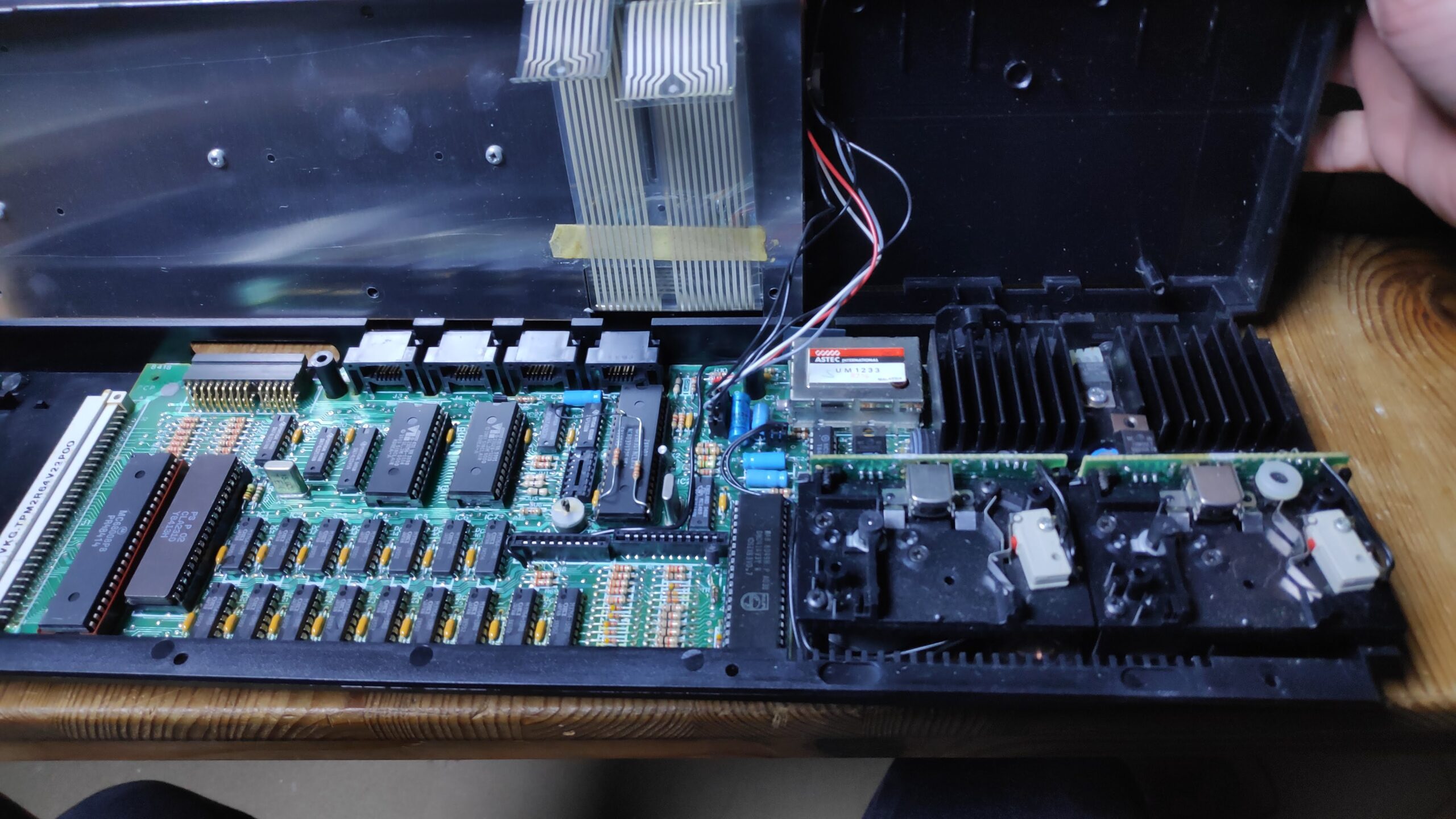
Looks failrly clean with just a bit of dust which is to be expected after over 30 years but no serious signs of failure such as leaking capacitors or burnt out components. A courtesy dust off with a small paint brush and I took the opportunity to clean the microdrive heads with some isopropyl alcohol and cotton buds.
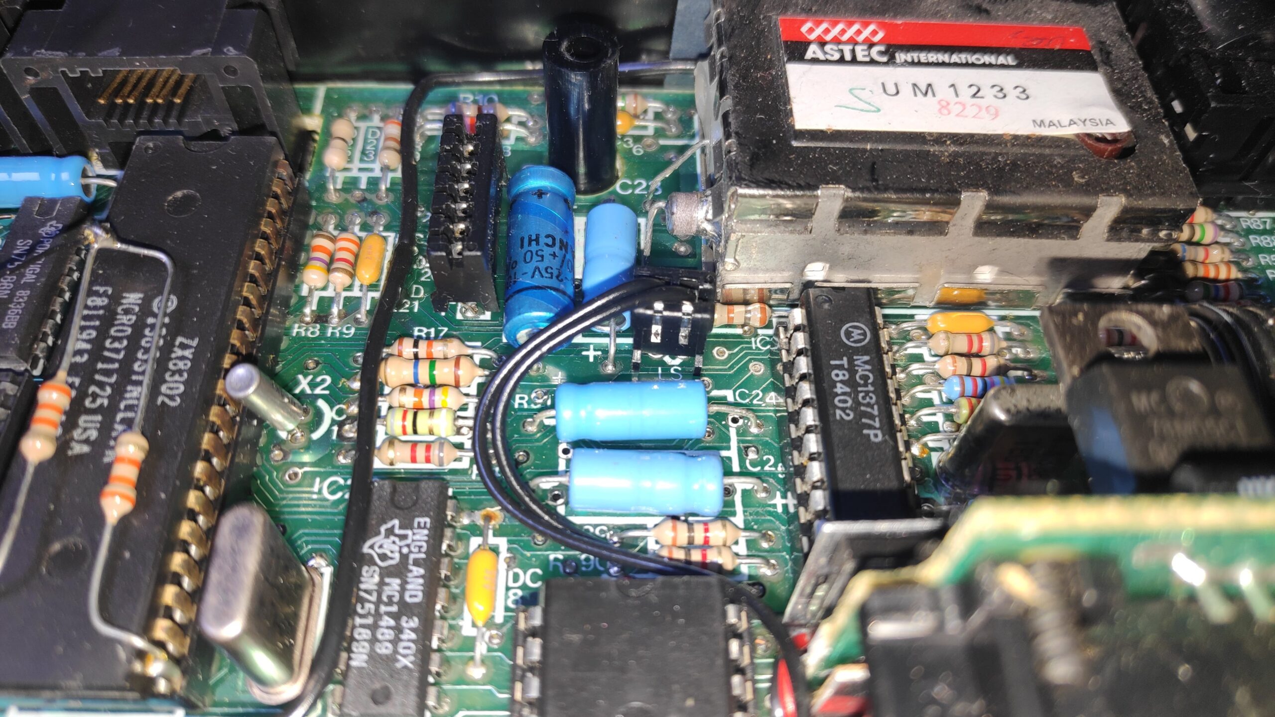
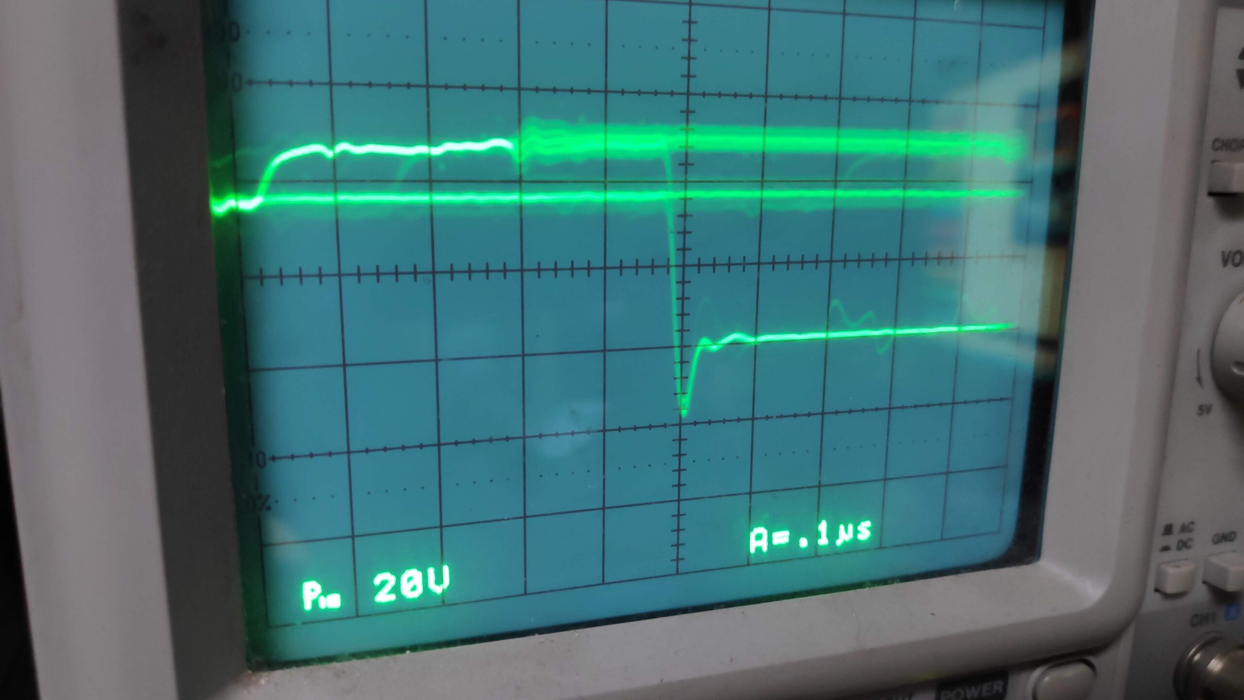
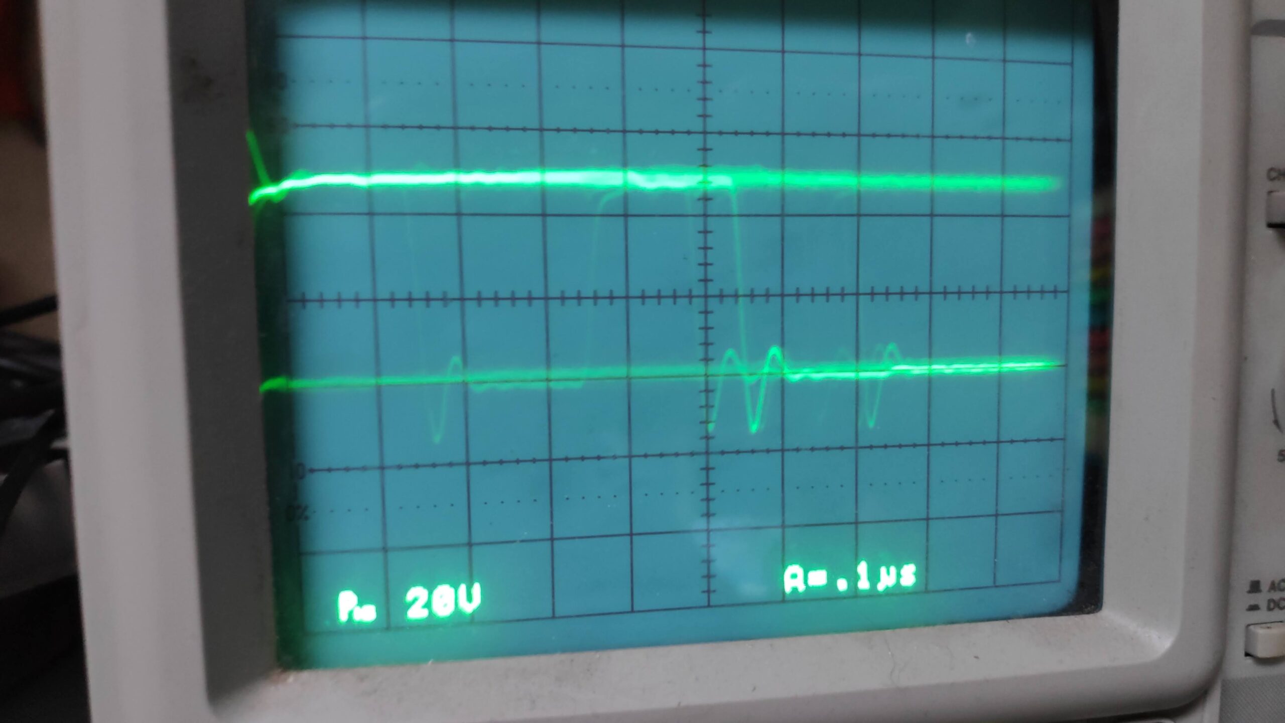
First port of call was to check the voltages. The 7805 was checked first with 9.5v input and 5v out so that looked ok. Next the ram chips with pin 16 showing 5v on all chips. So far so good. Researching the symptoms it was likely the issue was either the logic chips or the ram chips. No guarantees of course so some courtesy checks on pin 2 (input / output) of the ram chips with an oscilloscope and things looked normal and consistant except for IC7 and IC14 which showed little or no activity as below
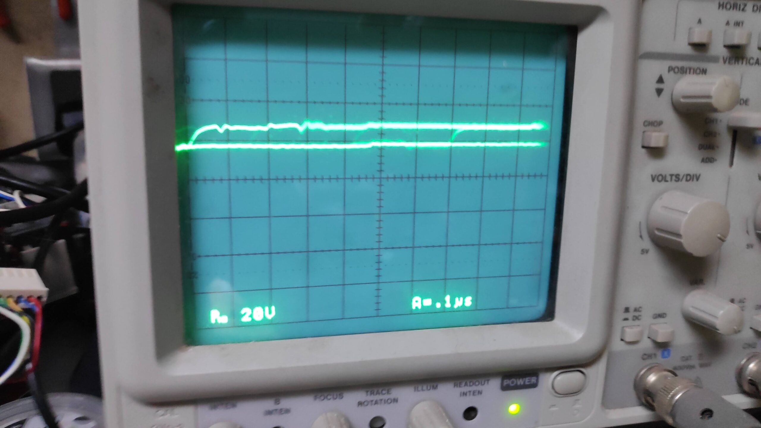
however all other ram chips showed activity but there was still the double thick line at the top as shown below .
The 68008 processor was showing normal activity and the voltages around the board were normal.
So I had a dilema of desoldering the suspect RAM chips or desoldering the logic chips. Most research suggested the logic chips as the most likely cause so I decided to desolder the 74LS257’s IC20,22. I then tested these with my trusty old TL866ii but they were fine so next was the 74LS245 IC21. Testing this revealed complete failure. So I socketed and replaced with a new one.
Testing with the scope now should the same activity (pin 2) on all ram IC’s. Notice just one thick line at the top.
Time to check on a TV and hey presto!.
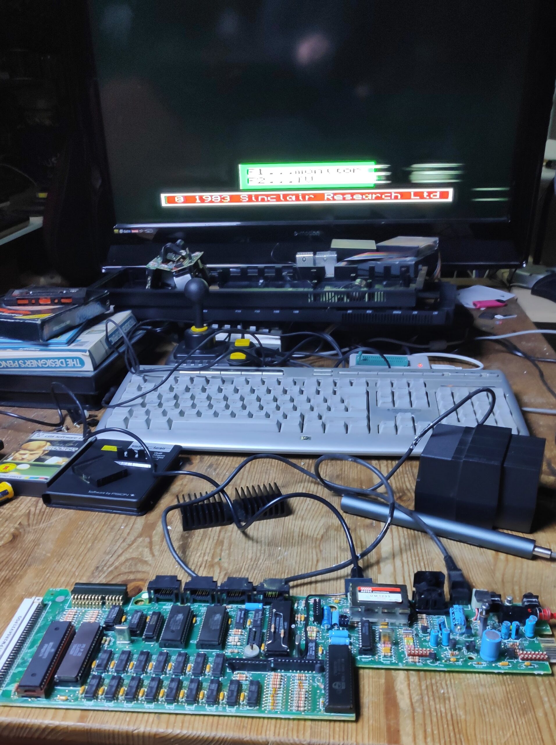
Success!!
The display is smudged but thats through the RF signal which isn’t the best so I moved to using a RGB cable.
A careful reassembly is required, watch out for the those microdrives as they are a pain to reconnect and note the power light connections as described above. My first attempt resulted in a constant running microdrive, so a quick turn off and inspect. Close inspection of the microdrive revealed a wire not inserted correctly or had popped out. Reinserting this corrected the proplem. Finally it was time for a load test.
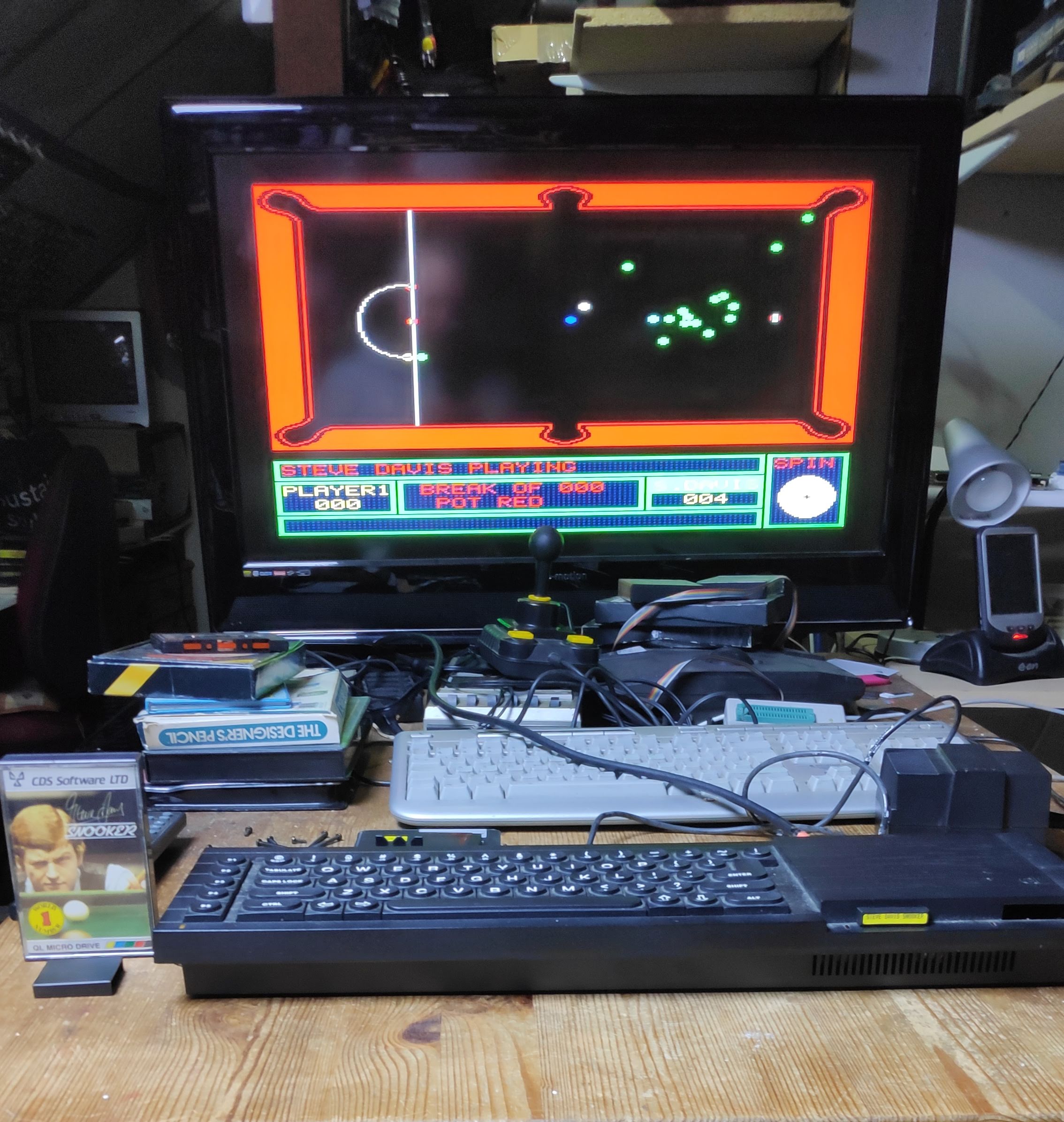
The displayed Image is much better with a RGB cable and inserting the supplied Steve Davis Snooker cartridge booted first time.
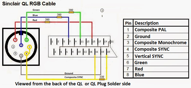
Finally I decided to take time on my RGB cable as I was getting a slight sideways flicker of the whole screen every few seconds. I suspected the the verticle blanking signal was weak from Pin 4 to scart pin 16 so my fix is to connect Pin 1 and 4 to the blanking pin 16 on the scart and now the image is completely stable.
Hoping this helps someone in the same situation.
#RetroHappyDay