
The 8256 only has 256k of memory, one single side floppy drive which was faulty on mine and so was the first order of business.
The following describes the steps I went through to get it working just as I wanted with extra memory, a gotek drive which coexists with the existing 3 inch floppy drive and a switch to allow booting from the original floppy or the gotek.
Turning the machine on resulted in green screen but no signs of booting from the one floppy disk that came with the system when I bought it which was Locoscript on one side and CPM on the other. At least the spindle was spinning on the drive when I turned it on, which is a good sign the belt has failed.
Removing the drive is a simple matter of removing the back case which is secured with 5 screws. Two recessed at the top , two at the bottom and one small screw below the printer port. The back came off and revealed relatively clean innards.
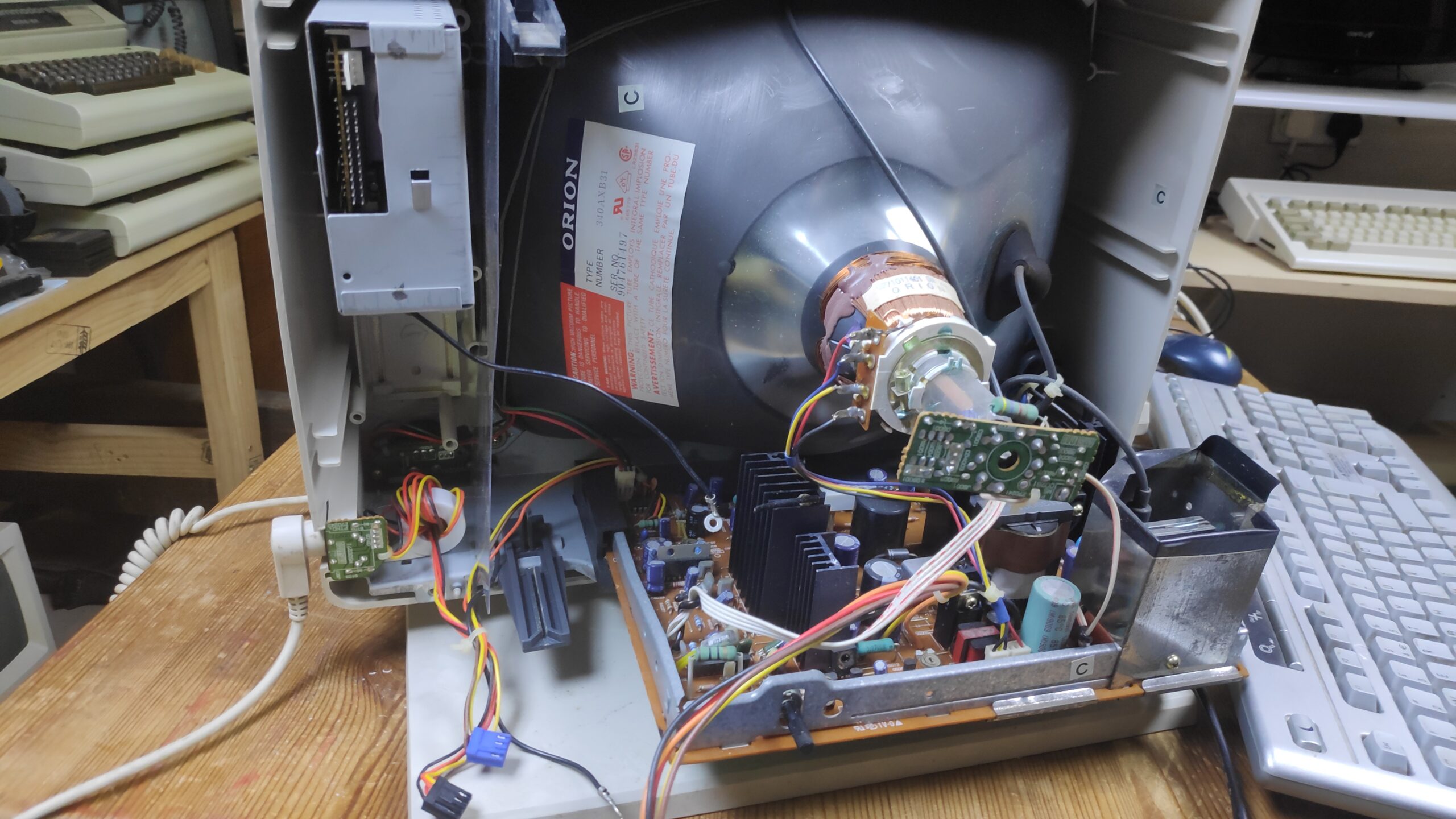
First I removed the power and cable leads and then the drive can be removed by removing the 4 screws around the drive casing and one earth lead screw.
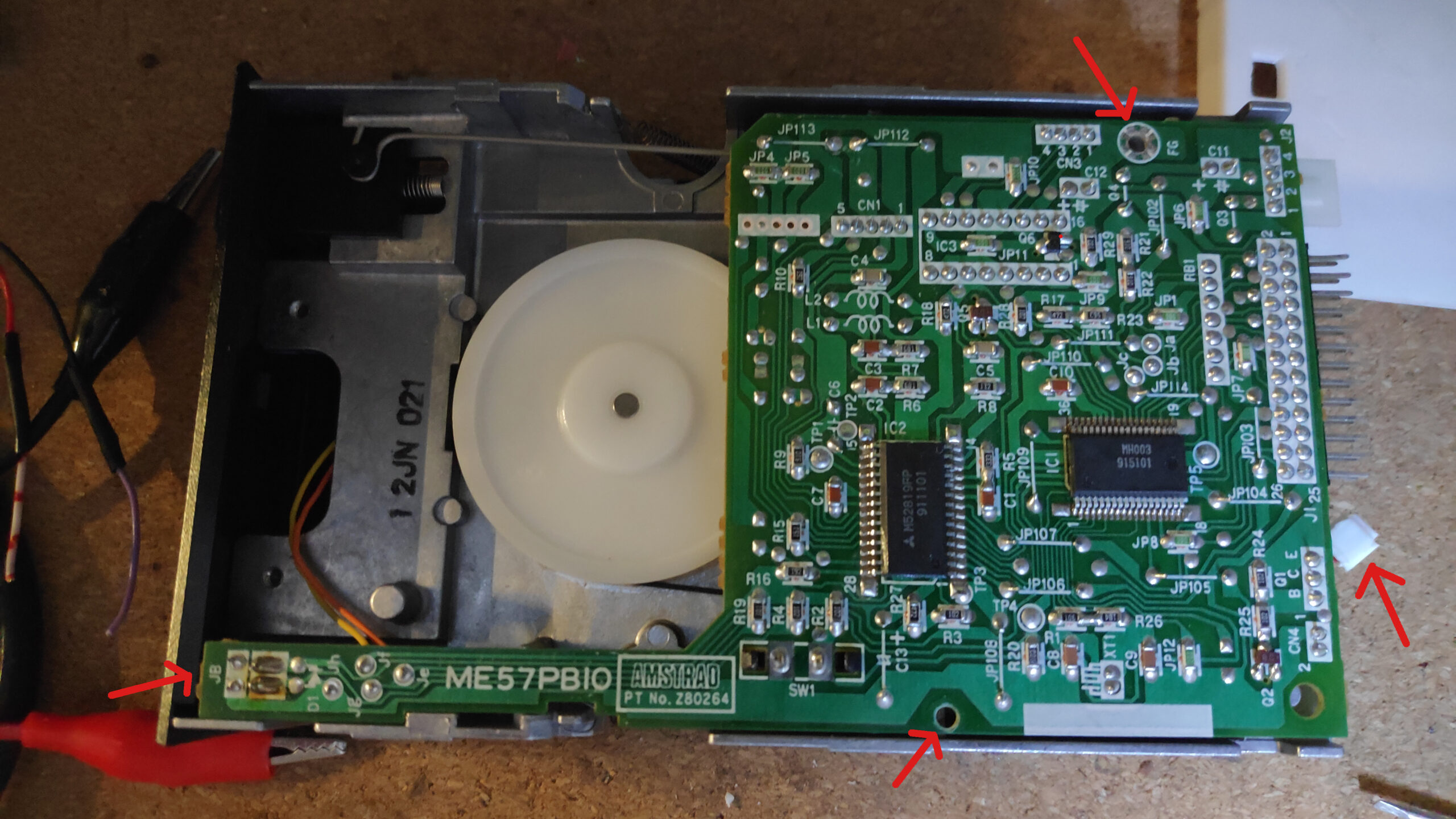
Once removed the casing is removed remove the two outer screws to slide out the drive. The big white spindle is visible which was missing a drive belt but £2-£3 from ebay supplied a Amstrad 3inch drive belt. To install it simple remove the 2 circuit board screws the right side cable connector and then slide the circuit board to the right so the drive LED on the left is exposed. You may need to flex the board to free the LED. The board can then be raised slightly giving access to slip the belt around the spindle and the motor. Reassemble, connect and test if the machine boots.
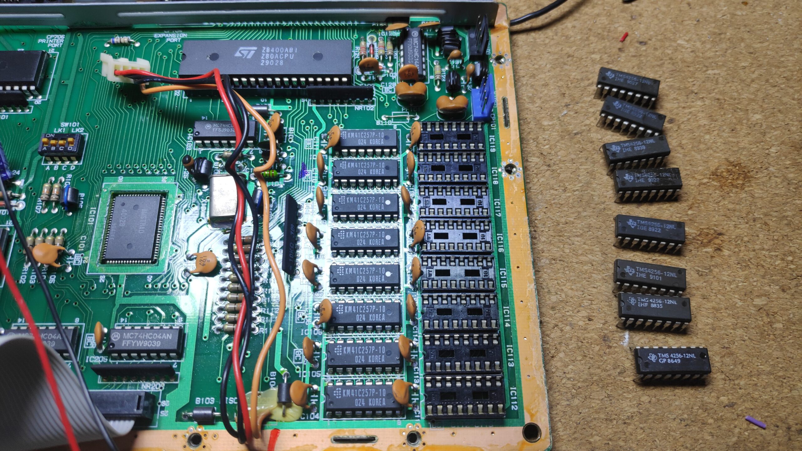
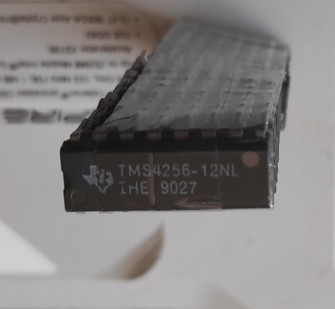
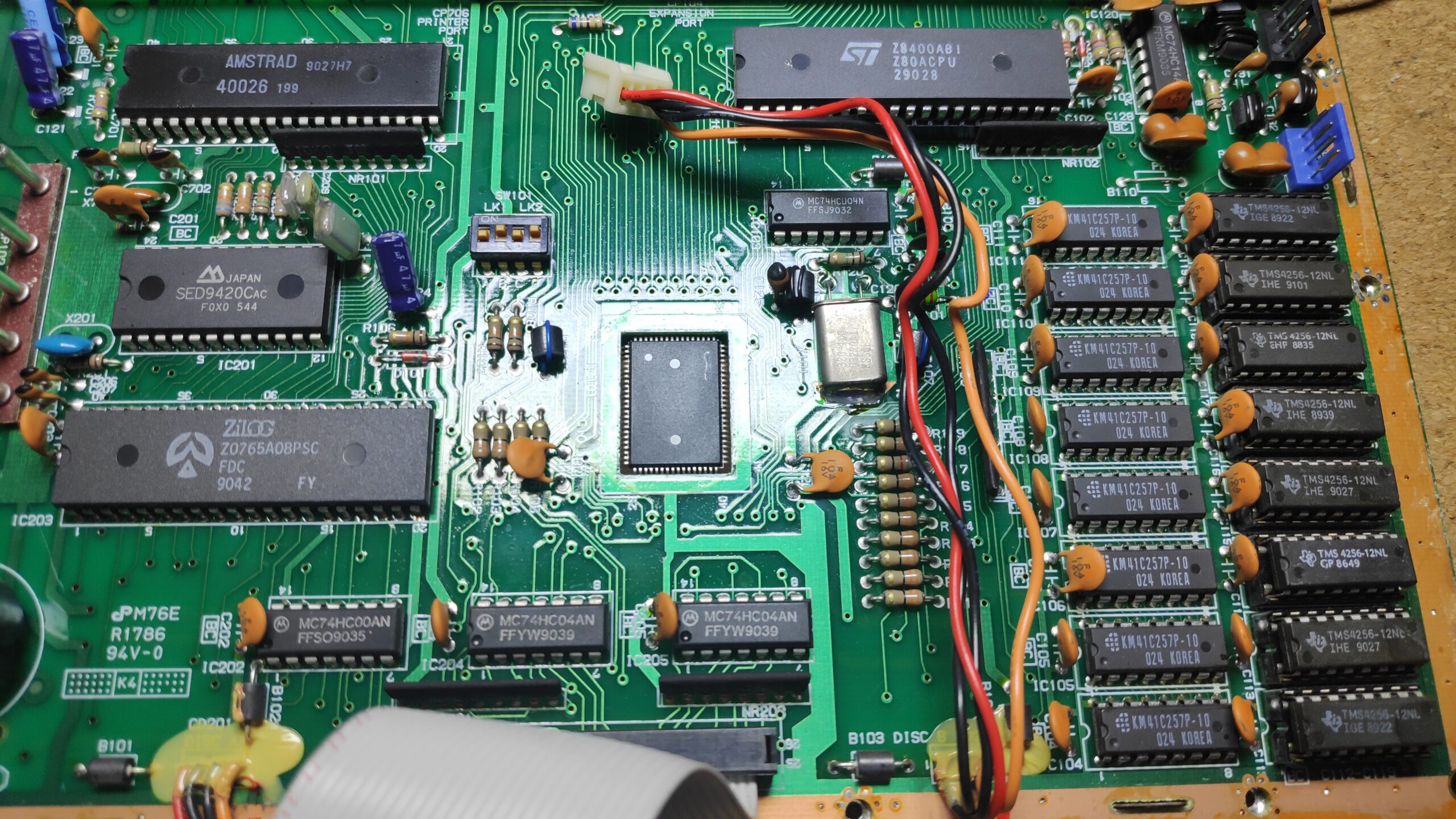
A simple upgrade is to add another 256K by simply installing 41256(TMS4256) or equivalent ram chips in the unpopulated sockets on the motherboard. The Speed of these ram chips should not be slower than 150ns mine are 120ns hence the 12NL marking. Ensure the dip switches in the middle of the motherboard are set to B, D on and A, C off, See top left of the photo in 256k configuration A, D on.
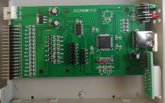
I had one Gotek left which had been sitting on a shelf for a year before I realised after removing its case, that it was a FDD-UDD U144K model which is 1) Not what I ordered and 2) A real pain in the arse to flash and setup. Thanks! Aliexpress and thanks to me for not checking the item when it arrived. I should have received a SFR1M44-U100K which is much easier to work with but hay ho it is what it is. The board is weird and far from the ideal Gotek model for this project as its difficult to flash and the original 7 segment display is hard soldered in and therefore the replacement OLED needs soldering in, also the contacts are not labelled so need to be determined.
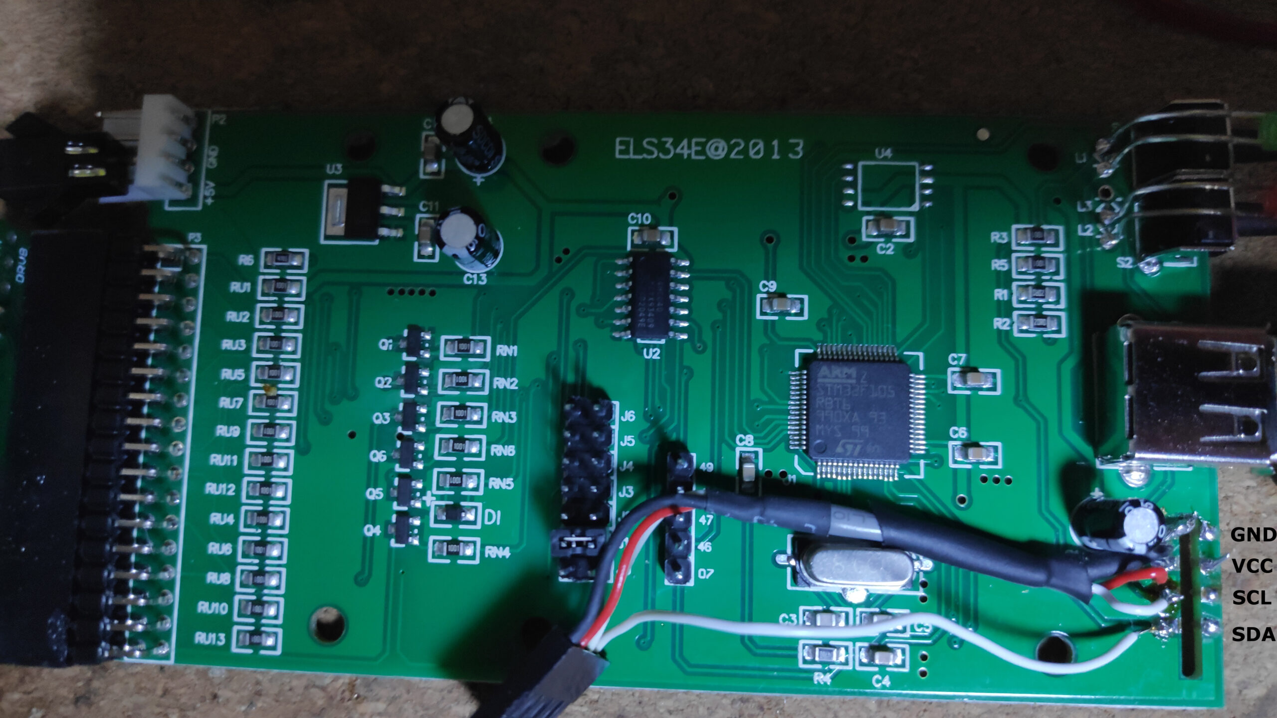
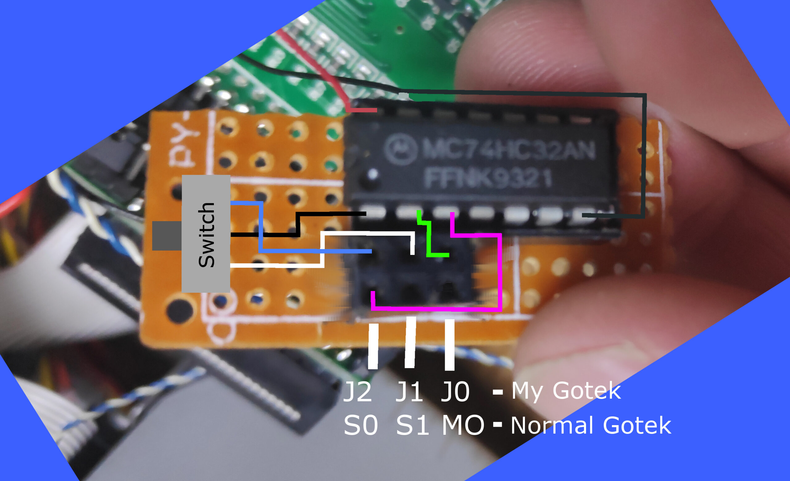
A bit of testing revealed the connection points labelled below bottom right.
Flashing the FDD UDD U144K
The usual gotek flash points are unavailable and I didn’t have a STM V2 usb stick which apparently makes things easier as you can connect to the 5 pin header. See here.
I didn’t have the STM V2 stick so had to connect direct to the ARM chip on pins 6 TX and 7 RX connected to a USB to serial adapter see claaaaay’s comment on the same link just past half way down with images of the connections. What a pita! compared to the normal Gotek.
Once programmed you should be able to disconnect the existing drive and connect to the gotek to the PCW and test if it works(WARNING!!!!! see below to power the Gotek). The jumper needs to be on the J0(MO) pins of the gotek.
WARNING!!!!! make sure to rewire the power connector as it has 12v(Red wire) in place of the 5v required for the Gotek but there is a 5v pin(Orange wire) you can swap in. Do not connect 12v to the Gotek!!!!!!
Floppy Drive with Gotek A B Switch
The intention is to allow the system to boot from the original floppy drive or switch to boot from the Gotek but with access still to the other drive as B.
The switch connections below set the floppy drive to be A or B.
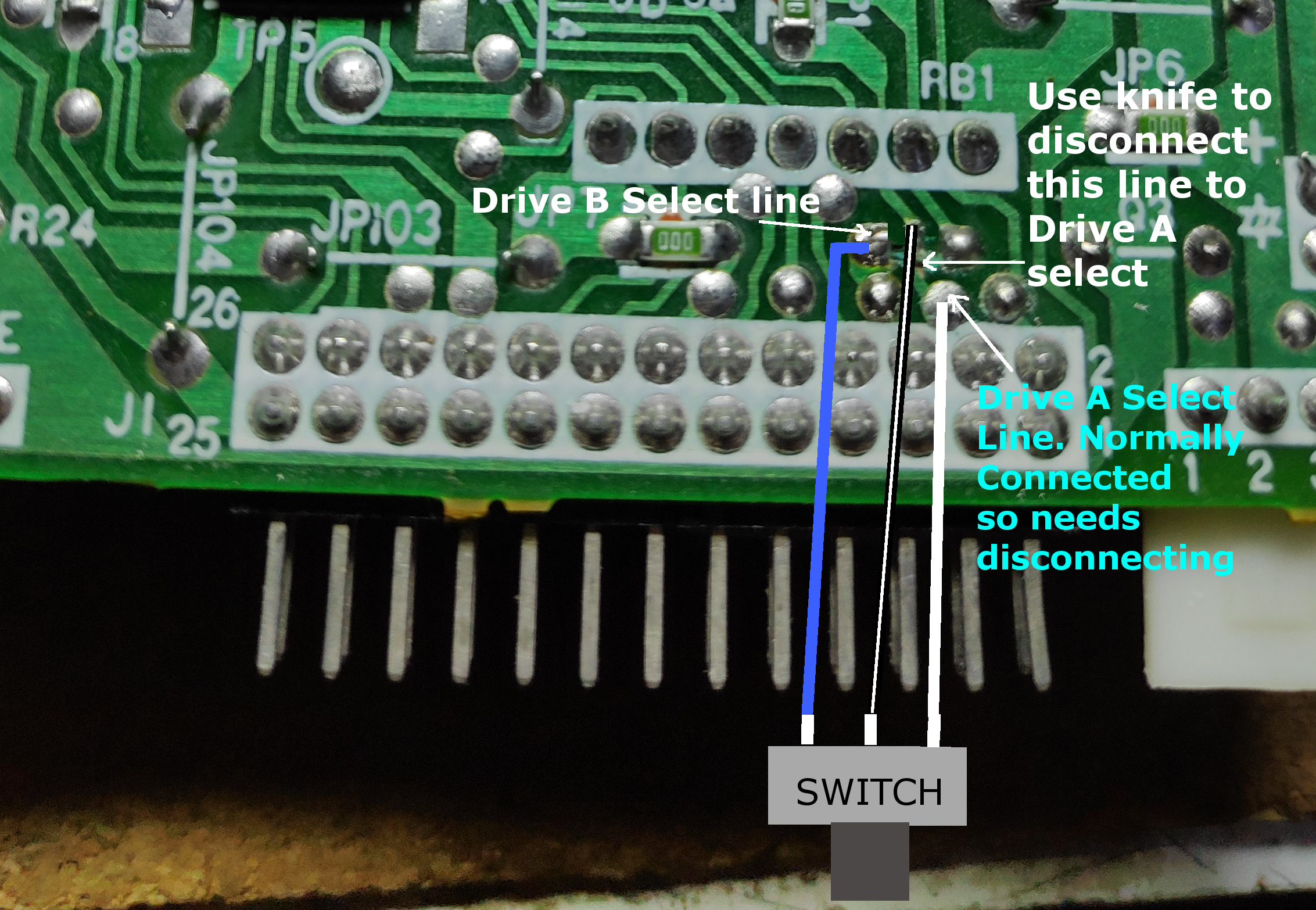
There are 6 connectors on the DPDT slide switch. 3 connect to the drive above and 3 connect to the circuit below. With the floppy drive AB switch in place you can test it by connecting both the Gotek and the floppy drive to the PCW. Manually set the jumpers on the Gotek to Drive A (MO and S0 normal Gotek ) or (J0 and J2 my Gotek) then set the floppy drive to B(Switch to blue wire). Remember to use the correct plug(5v modified) for the Gotek. Turn on the machine and select a CPM DSK on the Gotek (Preferably CPM107H.DSK ) . two drives should be reported. N.B. the second drive B probably wont be accessible yet.
Turn off the machine switch the floppy to Drive A and set the Gotek jumpers to MO and S1 and retest turning on the machine. You will need a CPM boot floppy.
Making a circuit to switch the Gotek side to A or B
The research is from here. So thanks go to Fabrizio Di Vittorio. The idea is that the MO motor signal is OR’d with the S0 or S1 signal from the drive cable of the PCW and output to the MO,S0, S1 on the Gotek side of the 14pin connector which are wired together so just a connection to S0 (Gotek side) is wired below. The switch switches between S0, S1(PCW side black wire) being connected to the first input of the or gate on the (74LS32) and the MO signal (Green wire) connected to the second input. The output (purple wire) goes to the Gotek S0(Actually MO, S0, S1 connected together, effective drive enable). Apologies if this is as clear as mud. Here’s a diagram. The red and grey wires are 5V and ground taken from the power connector on the Gotek.
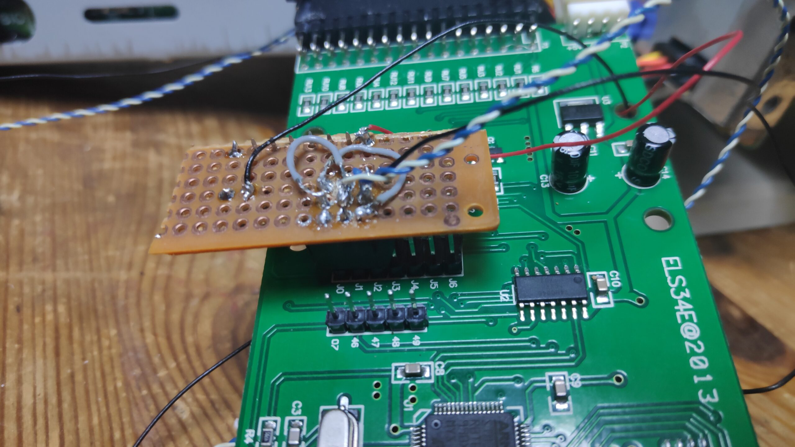
The circuit in situ. Excuse the sloppy soldering. Will tidy it up later, honest.
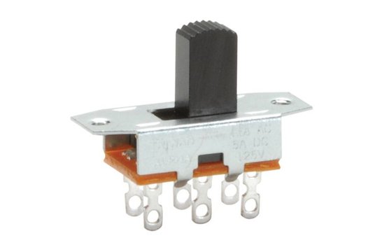
This is the DPDT slide switch I used with the 3 connections for the original drive and 3 connections for the Gotek. The center pin is common (Black wire) with the outer pins for Drive A (White wire) or B (Blue wire)
Finally to get the B Drive Working
Ok so the issue I had was the PCW boot boot fine from the Gotek or the floppy drive but the B drive was inaccessible. I though this was hardware related such as a bad connection but it turns out its CPM on the disk which needs modifying.
Get a copy of CPM 1.07H DSK, file J15CPM3.EMS, B180.FIB.
I used ManageDSK which is a PCW disk read/write utility.
Read in the CPM 1.07H.dsk file and remove the J17CPM3.EMS file. Then add in the J15CPM3.EMS and the B180.FIB files and write the disk. Transfer to your gotek USB and the system should boot fine from the Gotek and be able to access the Floppy drive.
You can then make a floppy CPM disk and ensure the same files are copied i.e J15CPM3.EMS and the B180.FIB.
Apparently the B180.FIB sometimes needs to be B180.FID. So try this if you are having trouble.
My working CPM version with files are available here
Here is the finished project accessing both drives.
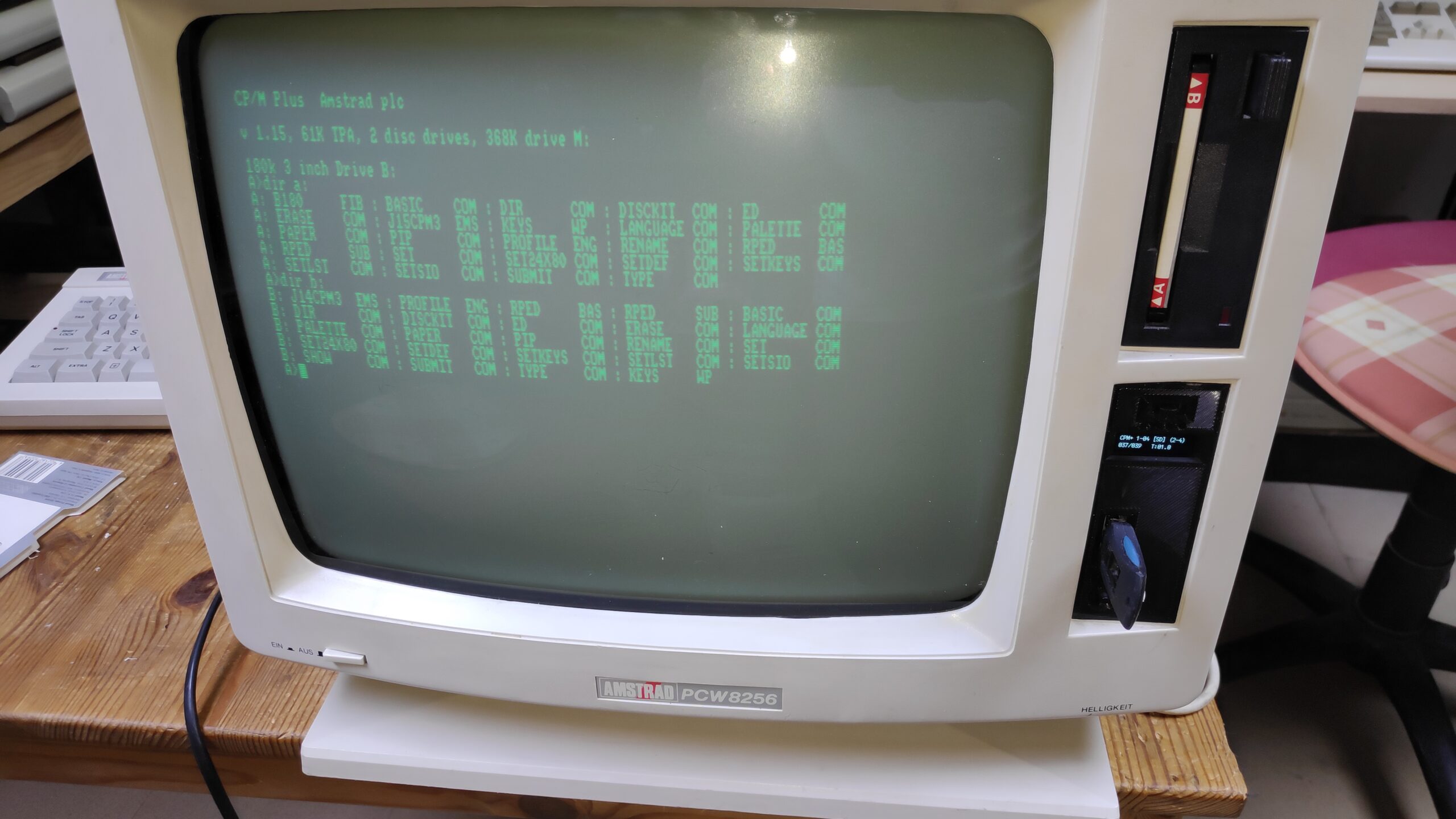
Job done! time for fun.
Hopefully this will help someone in a similar situation and save them some time. Please note that doing any of this project is at your own risk so please be careful especially with the old crt screen which is extremely!! dangerous. CRT discharge videos are available on youtube.
Enjoy.